|
|
Post by madpatty on Jul 16, 2018 8:39:05 GMT -5
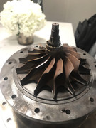
Hello All, I got my hands on a used/scrapped Capstone C30 gas turbine. Obviously i had to tear it down to see what's inside especially those air foil bearings that don't need any lubrication cooling etc. Below are some of the pics after teardown.     Cheers. |
|
|
|
Post by madpatty on Jul 16, 2018 8:41:21 GMT -5
|
|
|
|
Post by madpatty on Jul 16, 2018 8:43:18 GMT -5
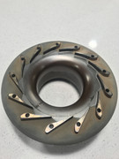
Fuel Injectors.   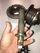 They have 2 inlets(For fuel and for air). They use air bled out from the compressor and inject a premixed mixture into the combustion chamber. A nice simple design. Cheers. |
|
|
|
Post by madpatty on Jul 16, 2018 8:51:21 GMT -5
I wasn't able to remove the combustion chamber from the big heat exchanger cum external pressure casing. What appears to me is this thing is manufactured in sort of a sealed fashion where everything is packed in from,say, one side of the big cylindrical metallic casing and then welded shut. I looked inside using my phone camera and found severe heat damage on the walls of combustion chamber at certain location(especially at locations directly in line with, where fuel injectors inject fuel).   |
|
|
|
Post by madpatty on Jul 16, 2018 9:20:52 GMT -5
There is a minor problem. I am not able to loosen this 12 point nut that is probably keeping the rotor at it's place.  Can someone shed some light on it as to how these are usually assembled. Maybe it need some heating etc. but it's a small 3/8" thread size nut and requires a 7/16" 12 point spanner. I used all forces on it yesterday and it strangely didn't move at all. Maybe i am doing something wrong. I am pretty sure i was trying to rotate it in the right direction as looking at the threads. Any input will be appreciated. Cheers. |
|
|
|
Post by turboron on Jul 16, 2018 9:20:53 GMT -5
Madpatty, thanks for sharing the photographs. Very interesting.
Thanks again, Ron
|
|
CH3NO2
Senior Member

Joined: March 2017
Posts: 455 
|
Post by CH3NO2 on Jul 16, 2018 9:40:01 GMT -5
Scored!  |
|
|
|
Post by Johansson on Jul 16, 2018 10:36:35 GMT -5
There is a minor problem. I am not able to loosen this 12 point nut that is probably keeping the rotor at it's place. Can someone shed some light on it as to how these are usually assembled. Maybe it need some heating etc. but it's a small 3/8" thread size nut and requires a 7/16" 12 point spanner. I used all forces on it yesterday and it strangely didn't move at all. Maybe i am doing something wrong. I am pretty sure i was trying to rotate it in the right direction as looking at the threads. Any input will be appreciated. Cheers. Interesting project! I suspect that there is thread locking paste in the nut so heating it up first with a hot air gun is probably a good idea. Cheers! /Anders |
|
|
|
Post by madpatty on Jul 16, 2018 12:46:35 GMT -5
There is a minor problem. I am not able to loosen this 12 point nut that is probably keeping the rotor at it's place. Can someone shed some light on it as to how these are usually assembled. Maybe it need some heating etc. but it's a small 3/8" thread size nut and requires a 7/16" 12 point spanner. I used all forces on it yesterday and it strangely didn't move at all. Maybe i am doing something wrong. I am pretty sure i was trying to rotate it in the right direction as looking at the threads. Any input will be appreciated. Cheers. Interesting project! I suspect that there is thread locking paste in the nut so heating it up first with a hot air gun is probably a good idea. Cheers! /Anders Maybe there is a thread locking paste. But this is the turbine side which already gets heated so I don't know if that paste would have stayed. Also it's a weird design where the shaft is passing through the turbine wheel rather than through compressor wheel. I thought turbines with shaft passage makes it weaker. Cheers. |
|
|
|
Post by turboron on Jul 16, 2018 14:15:55 GMT -5
madpatty, a hole in the bore of a wheel doubles its stress. Note that the large Allison/Rolls-Royce C30,C47 etc helicopter Titanium compressor wheels do not have a hub bore for that reason.
Thanks, Ron
|
|
ripp
Veteran Member
I'm sorry, I don't speak english, so I torment you (and myself) with a translation program,Sorry
Joined: January 2013
Posts: 230
|
Post by ripp on Jul 16, 2018 14:58:47 GMT -5
|
|
|
|
Post by madpatty on Jul 16, 2018 15:51:31 GMT -5
The measurements with not proper measuring tools are as follows-
Comp. Inducer ~60mm
Exducer ~ 92mm
Turbine
Inducer ~115mm
Exducer ~75mm
Cheers.
|
|
jeffreyguy
Junior Member
Joined: June 2018
Posts: 51
|
Post by jeffreyguy on Jul 16, 2018 22:14:00 GMT -5
It sure is neat to see how the real ones go together
|
|
ripp
Veteran Member
I'm sorry, I don't speak english, so I torment you (and myself) with a translation program,Sorry
Joined: January 2013
Posts: 230
|
Post by ripp on Jul 17, 2018 0:37:05 GMT -5
The measurements with not proper measuring tools are as follows- Comp. Inducer ~60mm Exducer ~ 92mm Turbine Inducer ~115mm Exducer ~75mm Cheers. Thank you very much Cheers Ralph translate.google.com |
|
|
|
Post by Johansson on Jul 17, 2018 2:16:01 GMT -5
Maybe there is a thread locking paste. But this is the turbine side which already gets heated so I don't know if that paste would have stayed. Also it's a weird design where the shaft is passing through the turbine wheel rather than through compressor wheel. I thought turbines with shaft passage makes it weaker. Cheers. Ahh, my bad! I assumed it was the comp nut.  |
|