micphijam
Member

Joined: October 2017
Posts: 16 
|
Post by micphijam on Aug 13, 2019 21:50:28 GMT -5
It can work , but you'll probably experiece large explosions as a combustor full of gas ignites instantaneously :-( Haha! Exciting and petrifying what a combination! Sounds like I might need to look at other plans |
|
|
|
Post by racket on Aug 13, 2019 23:04:57 GMT -5
You want the ignition point close to where the gas is injected so that only a small volume of combustable gas mix is ignited and has space to expand out within the flametube .
With my micro engines I only inject the preheat gas into a few of the evap tubes at the "bottom" of the engine so that only a portion of the flametube has combustable mix that can "explode" .
|
|
micphijam
Member
Joined: October 2017
Posts: 16
|
Post by micphijam on Dec 27, 2019 1:48:13 GMT -5
Its been a while since posting. The wife returned and i hadn’t fired the engine up yet. My biggest challenge has been oiling.. I bought an ebay special 12v “scavanger” pump.. but at 13 L/m flow rate, I was getting oil pressure over 100 psi b4 blowing a fuse.. This was because the turbo inlet orifice was so small. I then used a pwm (pulse width modular) controller to supply a peak volts and amps to the pump, but in blocks rather than a solid amount.. I then spent forever dealing with oil leaks. Anyway, Christmas eve, I had a mate over from Sweden. And we fired it up! I have an Exhaust gas temp sensor, and Oil pressure.. on startup, EGT temps spike to 1100c + before it gains rpm and settles down. Sitting at 6-700c pre turbo. Regardless of rpm. The end cap is getting red hot, ill have to bend some flame tube cooling holes upwards. Here is a YouTube link to the video of my longest sustained run so far. youtu.be/0yxuKvBGou0 |
|
micphijam
Member
Joined: October 2017
Posts: 16
|
Post by micphijam on Dec 27, 2019 1:55:35 GMT -5
And here are some other photos. A night time startup flame, and the colour of the flame tube.. The colour appears good with the dilution holes doing their job, there isn’t much heat colouring beyond them. One thing I noticed the flametube is much hotter on the far side of the inlet than the nearside, even at the top. I’m not sure what, if anything I can do to combat this.    |
|
slittlewing
Senior Member
Joined: November 2017
Posts: 458
|
Post by slittlewing on Dec 27, 2019 9:57:44 GMT -5
Nice work, well done on getting it running!
What propane injector are you using? The end where you are injecting it looks too hot! I am guessing it’s radial injection, I had a similar problem and am now injecting at 45 degrees like a cone (untested yet though)
Cheers
Scott
|
|
BFTO
Veteran Member
Joined: February 2016
Posts: 128
|
Post by BFTO on Dec 27, 2019 10:48:50 GMT -5
You should consider more holes in the top of FT to cool the lid and/or move the injector a bit down the FT, can you show us your propane injector?
600-700C, was that TIT-temp? You should consider to remove the probe and install it after the turbine instead, the probe can get damage and wreck your turbine.
|
|
micphijam
Member
Joined: October 2017
Posts: 16
|
Post by micphijam on Dec 27, 2019 15:44:54 GMT -5
Thanks fellas! Ive been having a blast with it running.
Yea the propane injector was a radial style. Pinched end etc. ill take a photo today.
But problem solved, I drilled a couple more cooling holes at the to of the FT and bent them up towards the end cap, there is no glowing anymore! Thanks for the advice.
Yea the 6-700 is TIT. Ive ordered a V-band to install a nozzle.. I’ll relocate the sensor once I fabricate that.
In the meantime ill have to work on startup procedure. Those high temps 1100c+ I’m sure are going to melt a turbine wheel.
My reading on this says
1. Oil
2. Ignition
3. Fuel with blower near by but not sealed against inlet
4. Upon ignition, move the blower closer ensuring Flame stays lit
5. Once rpm increases pull back
|
|
|
|
Post by racket on Dec 27, 2019 17:09:40 GMT -5
Hi
Thats a fairly "fat" turb scroll compared to the comp scroll , so theres a chance you'll be flowing more towards the choke side of the comp map with poorer efficiencies which will impact your turb temps .
Your delivery tube at the combustor really needs a diffusing funnel to spread the flow over a greater area as it tries to enter the space between flametube and outer can .
You need to have the starter sealed against the comp housing during spoolup , we need every bit of air pressure energy going into the engine , its that "pressure energy" which facilitates flow through the restrictive flametube wall holes.
Keep the blower attached until you have at least 5 psi of P2 pressure .
Congrats on getting her fired up , she's sounding sweet :-)
Cheers
John
|
|
micphijam
Member
Joined: October 2017
Posts: 16
|
Post by micphijam on Dec 28, 2019 5:55:32 GMT -5
Thanks for the input.
I will need to invest in some more instrumentation. I’m not currently running a boost gauge and i have an oil temp, but isn’t hooked up just
As i said, oiling has been the most difficult part of the whole exercise
|
|
|
|
Post by racket on Dec 28, 2019 15:37:53 GMT -5
Hi Michael
Gotta have a P2 gauge , its a safety issue , not as good as a tach but it'll provide some guidence as to rpm and possible overspeed , with a used turbo of unknown heritage its best to be modest with P2/rpm especialy if the turb stage is a bit on the large side as its possible to overspeed at rather modest P2s , I wouldn't be going above an ~2.5:1 PR in your case , so no more than ~22-25 psi P2 until you get more data on the engines performance .
Yeh, oiling is a vital component , without reliable pressure the engine is likely to fail :-( .........thats why I like to use an automotive oil pump driven by an electric motor , it has the pressure reliefs as well as the filter in a package that can cope with hot oil .
Cheers
John
|
|
micphijam
Member
Joined: October 2017
Posts: 16
|
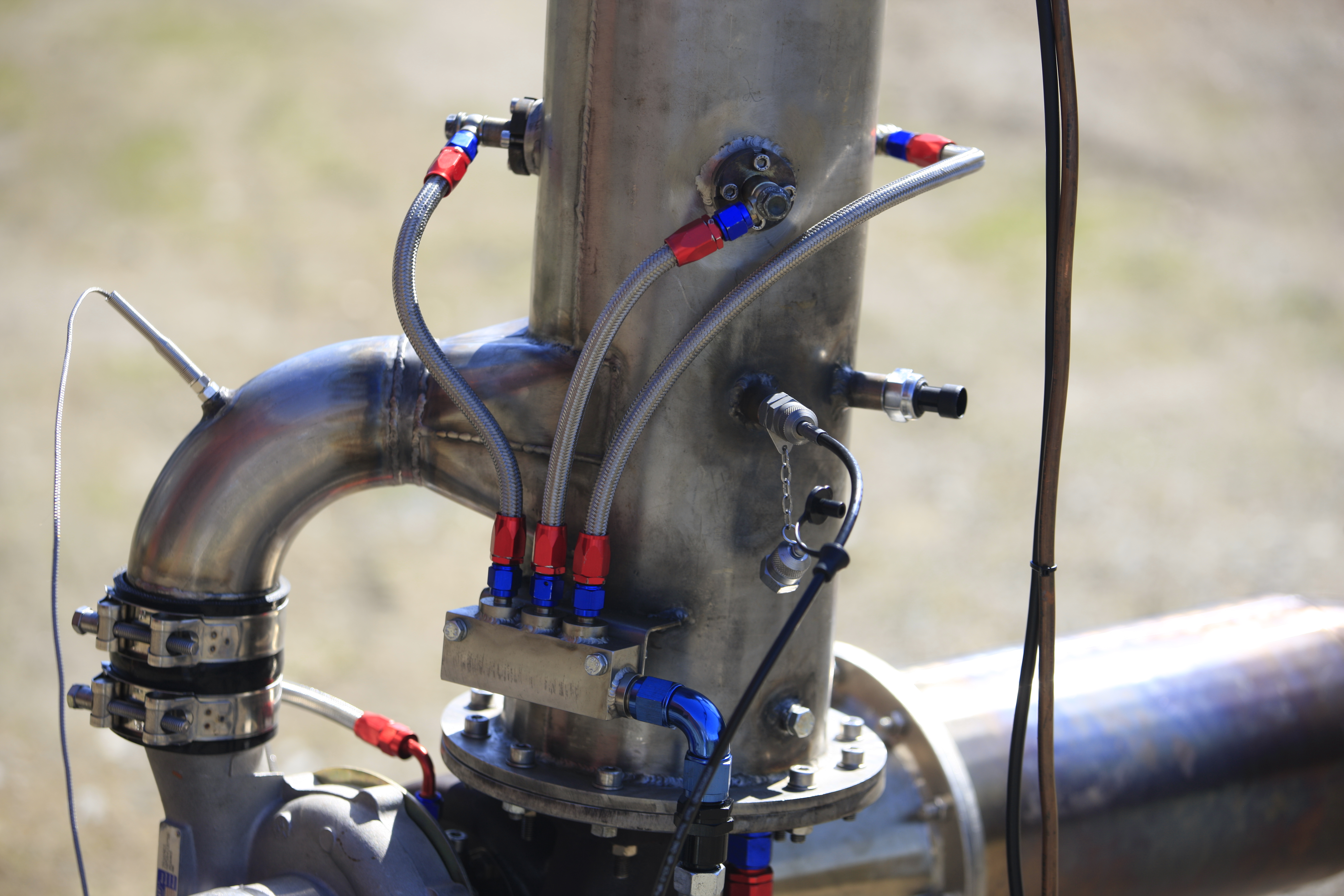
Post by micphijam on Jan 3, 2020 17:39:56 GMT -5
I received my 4” v band clamp and some 4” pipe and fabricated up the nozzle. I relocated the EGT sensor to TOT (from TIT). Im in the testing phase at this point to set the sizing of the nozzle before welding it in place. Im not much of a metal worker, but so far I’m quite happy with how it is panning out    |
|
|
|
Post by racket on Jan 4, 2020 1:11:00 GMT -5
A jet nozzle a few millimeters smaller than the comp inducer is a reasonable starting point for size
|
|
Colin Heath
Junior Member
Joined: January 2020
Posts: 77
|
Post by Colin Heath on Jan 15, 2020 14:51:37 GMT -5
I received my 4” v band clamp and some 4” pipe and fabricated up the nozzle. I relocated the EGT sensor to TOT (from TIT). Im in the testing phase at this point to set the sizing of the nozzle before welding it in place. Im not much of a metal worker, but so far I’m quite happy with how it is panning out Looking good and she runs! Will be following with interest |
|
micphijam
Member
Joined: October 2017
Posts: 16
|
Post by micphijam on Jan 16, 2020 1:18:11 GMT -5
I’ve been reading Model Jet Engins by Thomas Kamps as well as the documents from the “DIY TURBINE” post.. I want to undertake some calculations to determine the efficiency on the current setup. Unfortunately I don’t have a compressor map so I’m on the back foot. My current focus is on the compressor. I believe I need a p2 air temp sensor to be able to do the efficiency check. (Along with p2 pressure gauge) Then I believe I can then back calc the mass flow rate. Correct me if I’m wrong? What are common ways to measure air temp (on a budget)? I thought a k type probe might not react fast enough rover.ebay.com/rover/0/0/0?mpre=https%3A%2F%2Fwww.ebay.com.au%2Fulk%2Fitm%2F312709147224And a proper air intake sensor.. are cheap enough, they show there resistance values.. in a graph.. but what kind of gauge would I use to display the reading? www.efihardware.com/products/331/air-temp-sensor-Delco-14mmThanks! Michael |
|
|
|
Post by racket on Jan 16, 2020 3:07:23 GMT -5
|
|