nersut
Veteran Member
  
Joined: September 2012
Posts: 223
|
Post by nersut on Sept 2, 2014 20:44:37 GMT -5
Hi Eric Go BIGGER :-) Cheers John Why not?  I also now have a nice Holset HX55 for my turbocharger collection for free, "dumpster dive"  Cheers Erik |
|
nersut
Veteran Member
  
Joined: September 2012
Posts: 223
|
Post by nersut on Sept 2, 2014 20:48:11 GMT -5
Hi Erik, I wonder if you have cleaned off the nice oil flow traces in the diffuser section of that T1810 that you have pictures of on your July 1 post? If not, would it be possible to get a few close up shots of the oil traces on a diffuser passage from both the sides of the case? I have a VT50 that I think has some nice oil traces on it that I need to go out an take some pictures of. Those traces are great for "seeing" how the flow scrubs the wall or doesn't. I can't zoom in on the pictures you posted, so I can't tell if that is maybe a wake region formed due to high flow rates or maybe it's a tripped flow due to the entrance area of the diffuser (since there seems to be some clean spots in the center of several diffuser passages entrances). Either way it is really neat to look at! Thanks! Chris Hi Chris I still have some pictures of the T1810's compressor & diffuser vanes. 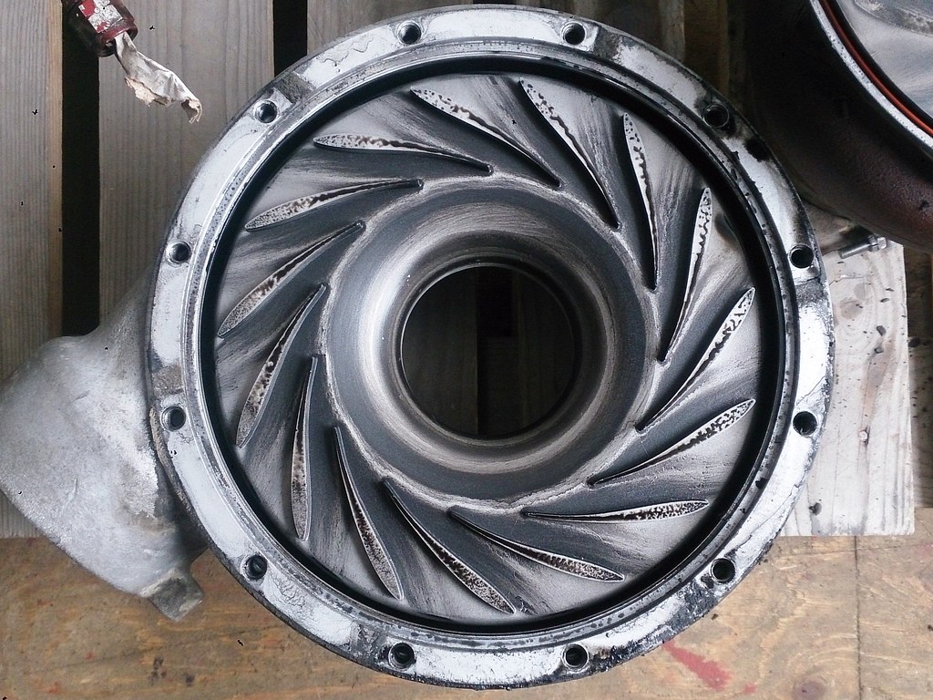 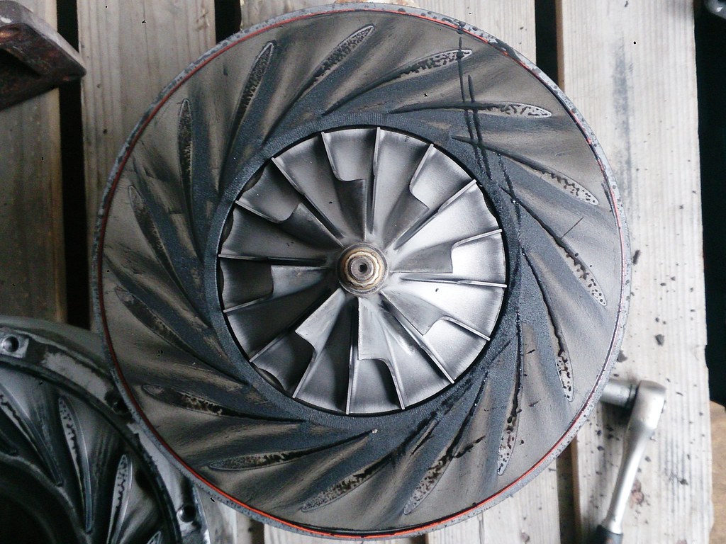 I can take more pictures if you need some specific areas. Cheers Erik |
|
|
|
Post by finiteparts on Sept 2, 2014 21:27:07 GMT -5
Sweet~!
That looks much different than what I thought I saw in the smaller pictures. There is a distinct curvature of the bulk flow that doesn't truly follow the pressure side (concave side, the convex side is the suction side) of those vanes. The suction side is usually where you get the worst flow separation (just like the top of an airplane wing) and it definitely looks like you had some flow separation here as the flow tried to come around the leading edge of the diffuser vane...or maybe a corner vortex set-up and create a vortex tube down through the passage...or potentially even a shock wave or expansion wave formed at the vane leading edge and cause a flow separation.(?)
But, it's easier to see that there was likely a separation zone started near the 50-60% chord location on the suction sides that persisted all the way back.
Super interesting! I think this should help those of us that are trying to use vaned diffusers to really understand that the off-incidence flows can really disturb the passage flow rates.
If you don't mind, could you get a close up of just one good looking passage, on both the front cover and the back plate? Nothing critical, just curiousity. I will try to take a few pictures of my VT50 and my GTC-85 second stage diffuser, which both have some neat residues!
Thanks Erik, I really appreciate it.
~ Chris
|
|
|
|
Post by finiteparts on Sept 2, 2014 21:34:29 GMT -5
By the way, I need to go dumpster diving with you! Apparently you have better trash in your neck of the woods! ha! I have never found a HX55 in any trash can anywhere...the best I got was a large computer monitor that I grabbed to get the flyback transformer out of, but then found that is only had a bad fuse. I used it for years till I switched to a nice LCD screen. ~ Chis
|
|
nersut
Veteran Member
  
Joined: September 2012
Posts: 223
|
Post by nersut on Sept 3, 2014 9:50:25 GMT -5
Hi Chris LOL! Next by the HX55 on the ground was a V8 truck diesel engine with two nice K27 still mounted on the headers. Sure I can take some closeup pictures later today, no problem.  Cheers Erik |
|
nersut
Veteran Member
  
Joined: September 2012
Posts: 223
|
Post by nersut on Sept 3, 2014 19:01:01 GMT -5
Sweet~! That looks much different than what I thought I saw in the smaller pictures. There is a distinct curvature of the bulk flow that doesn't truly follow the pressure side (concave side, the convex side is the suction side) of those vanes. The suction side is usually where you get the worst flow separation (just like the top of an airplane wing) and it definitely looks like you had some flow separation here as the flow tried to come around the leading edge of the diffuser vane...or maybe a corner vortex set-up and create a vortex tube down through the passage...or potentially even a shock wave or expansion wave formed at the vane leading edge and cause a flow separation.(?) But, it's easier to see that there was likely a separation zone started near the 50-60% chord location on the suction sides that persisted all the way back. Super interesting! I think this should help those of us that are trying to use vaned diffusers to really understand that the off-incidence flows can really disturb the passage flow rates. If you don't mind, could you get a close up of just one good looking passage, on both the front cover and the back plate? Nothing critical, just curiousity. I will try to take a few pictures of my VT50 and my GTC-85 second stage diffuser, which both have some neat residues! Thanks Erik, I really appreciate it. ~ Chris Hi Chris Here is a couple of pictures for you as promised.  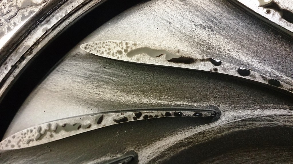 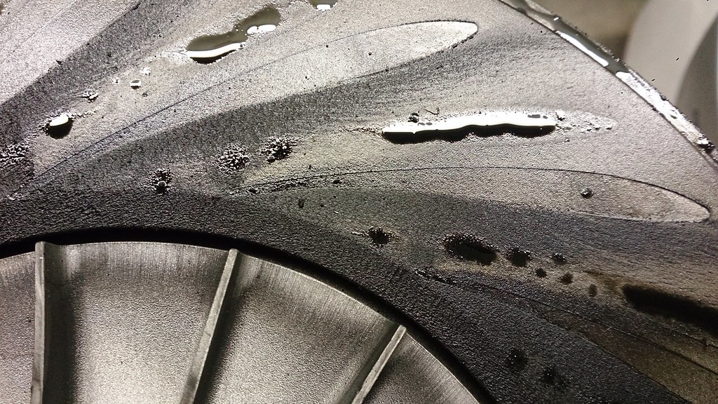 There is some false "echo" vane imprints (oily) on the base plate because I had remounted the front cover with a bit offset than previous location. Hope you can use it anyway. Cheers Erik |
|
rythmnbls
Veteran Member
  
Joined: August 2011
Posts: 145
|
Post by rythmnbls on Sept 3, 2014 19:22:54 GMT -5
Great photos, be interesting to compare the air traces with a cfd plot.
Thanks for posting.
Steve.
|
|
nersut
Veteran Member
  
Joined: September 2012
Posts: 223
|
Post by nersut on Sept 3, 2014 19:27:33 GMT -5
First steps on my next project! A raw metal piece for the base plate for the annular combustor, still needs some work on the lathe, 10 mm thick, 250 mm diameter. And a NGV from a marine/industrial turbocharger, it should fit after some minor trimming of the inner piece, 116 mm diameter (inner vane-to-vane) distance. 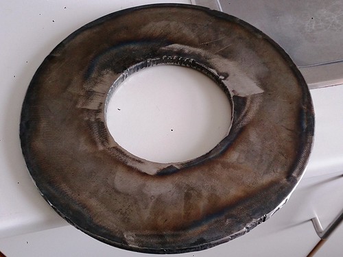 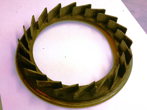 Cleaned up the T1810 turbo, sorry Chris!  Size comparison, Holset HX55 versus Garrett T1810. 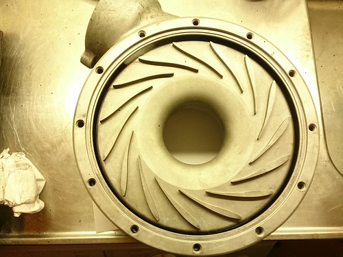 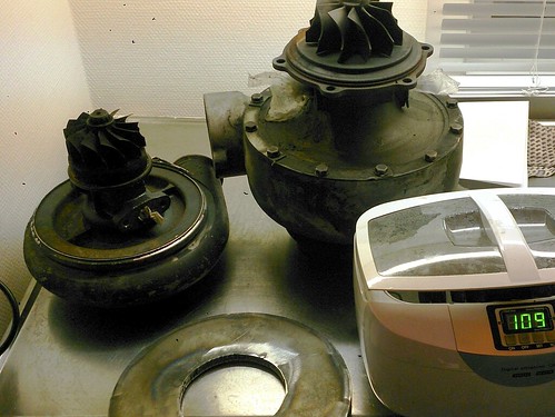 Cheers Erik |
|
|
|
Post by racket on Sept 3, 2014 20:14:56 GMT -5
Hi Erik
Thats what I like to see , big chunks of steel ready to be machined :-)
Is the NGV a match to the compressor wheel and its diffuser ?
Cheers
John
|
|
nersut
Veteran Member
  
Joined: September 2012
Posts: 223
|
Post by nersut on Sept 4, 2014 7:11:33 GMT -5
Hi Erik Thats what I like to see , big chunks of steel ready to be machined :-) Is the NGV a match to the compressor wheel and its diffuser ? Cheers John Hi John I still haven't calculated/measured the NGV size, only a visual check on the turbine wheel. The NGV have almost same height as the turbine inducer tips. Cheers Erik |
|
nersut
Veteran Member
  
Joined: September 2012
Posts: 223
|
Post by nersut on Sept 4, 2014 12:40:16 GMT -5
Here is a schematic drawing of the combustor. 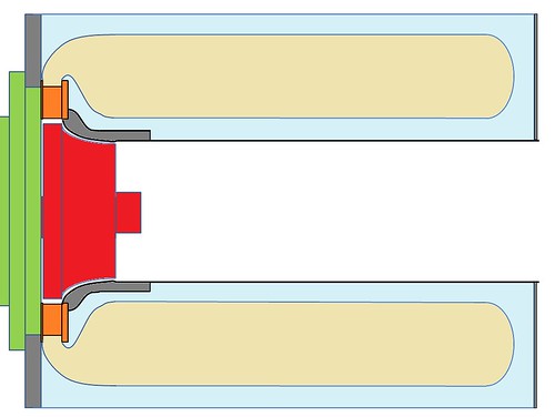 Compressor wheel 74,5 mm diameter, cross sectional area about 43,6 cm 2
43,6 cm 2 times three = 130,8 cm2Outer flame holder: 224 mm diameter, inner flame holder 118 mm diameter, cross sectional area about 285 cm2So the combustor area looks fine, but how long should it be at minimum? Cheers Erik |
|
nersut
Veteran Member
  
Joined: September 2012
Posts: 223
|
Post by nersut on Sept 4, 2014 17:33:15 GMT -5
Small progress made. Baseplate machined to fit the turbocharger flange. 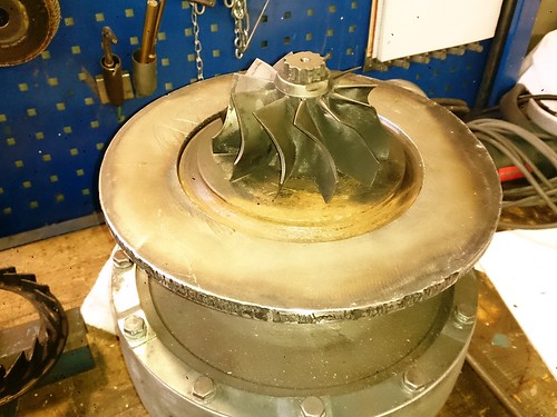 Here you can see the NGV sitting on top of the turbine tips, the NGV inner ring & base is machined so it can seat properly on the turbocharger. 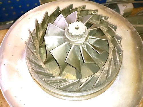 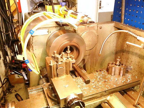 Cheers Erik |
|
ashpowers
Veteran Member
  
Joined: February 2011
Posts: 207
|
Post by ashpowers on Sept 4, 2014 17:43:41 GMT -5
Nice work bud! Glad to see progress! =)
|
|
|
|
Post by racket on Sept 4, 2014 20:56:27 GMT -5
Hi Erik
Looking good :-)
As for length of the flametube , it'll probably be determined by how well/quickly the fuel is atomised/vapourised , but probably no more than ~4 times the radial width of the flametube annulus , from your drawing it looks like the annulus is ~50mm wide , so maybe ~200 mm long for the main body of the flametube , the bit where it curves over and into the NGV is a bonus for dilution time , Anders and my flametubes are only ~100 mm long , with the main body only ~75mm , you have the luxury of having "unlimited" length to play with , so 200mm would be more than enough.
Are you going to use evaporators or spray nozzles ??
Cheers
John
|
|
|
|
Post by finiteparts on Sept 4, 2014 22:49:18 GMT -5
Hi Erik, Thanks for the extra pictures. I did some digging and the oil deposits on your turbocharger and on mine seem to indicate a similar flow separation on the suction side, over a similar length of the vane chord. This also appears very similar to an oil streak flow visualization test shown in a 1999 report by IHI on vaned diffuser selection on a large marine turbocharger. I think that the patterns on yours look slightly different in that the small triangular "clean" spots just upstream of the vane leading edges and then the sudden dark region suggest that your had a standing normal shock (bow wave like) adjusting the flow just prior to entering the diffuser channel and it's throat. The shock at the leading edge often "trips" the flow such that a rapid boundary layer growth occurs and that looks sort of like what is happening on yours. There also appears to be a "swirl" to the lines near the center which makes me think there might have been a corner vortex shed from the leading edge (on both sides) also. There is no way to really know and with the highly complex 3-d flow in these passages, it is really hard to speculate with any accuracy...but is is still fun to do! Here are some images of the first VT-50...notice the horrible cast surface! Aerothermal engineers have nightmares about surfaces smoother than that one!!! hehee! Also notice some of the vanes had damaged leading edges and the mice thought that it would be cool to set up a storage of acorns in the diffusers. I guess I need to go out and tape up all the openings on my turbos.    This is a second VT-50 that I have and notice that it has that chamfer after the impeller exducer like your T1810. I believe the purpose of this is for what is termed "pinch", which is a reduction of the diffuser passage height from what the impeller outer height is. Your turbo had much better oil lines...I did read a nice paper on GMs compressor development work where they outlined how they set up their "lampblack" injection so that they could inject it at specific conditions. I want to try it out in one of my turbo setups!  Finally, here are a few images of the Garrett GTC-85 second stage compressor and it's diffuser...obviously, it experienced a rub...this was due to a aft compressor bearing squirrel cage failure...I think that was due to the first stage compressor wheel liberating a chunk of a blade tip and then the out of balance condition was too much for the squirrel cage to handle. Note that there doesn't appear to be any separation from the leading edge...the deposits on this could be due solely to the reduced passage velocity and/or cross-passage pressure gradients.    Just an FYI...Boeing has some nice work out there showing Schlieren images of the shock formation in high pressure ratio centrifugal compressor diffusers. If I can find a public link, I will post it, because they are beautiful images of passages shock formations. The DLR Institute of Propulsion Technology has some neat images on their website...the first is a time stepping model of the flow into a diffuser... www.dlr.de/at/en/Portaldata/20/Resources/images/tech_ein/anima_diffusor_e.gifand the second is contour map of the Mach number...notice the cross-passage difference in mach number as you get towards the back of the passage. It looks close to what we are seeing on these systems. They don't suggest a mechanism of flow pattern for the contours though...so I am still sticking with the idea of flow separation/corner vortex. www.dlr.de/at/en/Portaldata/20/Resources/images/tech_ein/mabs_calc.gifEnjoy! Chris |
|