|
|
Post by Johansson on Sept 8, 2014 14:16:30 GMT -5
Lets get back to the bike build for a while.  I have been thinking a lot about the power turbine shaft bearings, Ash very kindly sent me a 20mm ID Allison bearing which is a top notch bearing. Buuuut.... ...adapting the 25mm diameter shaft will be very troublesome. The shaft needs to be ground down which effectively removes the key slot that the power turbine center piece locks on to, so I will have to mill a new slot and make a completely new power turbine center piece which took me quite a while to make. Grinding the shaft down will also prove a challenge since the pinion gear at the end of the shaft prevents me from fitting it in a lathe.  If I have to I´ll do it of course, but I would really want to try a simpler solution first. With the oil jet lubrication I somehow believes that the hybrid bearing with its plastic cage would have survived, after all the rear bearing looks like new despite getting the same treatment with heat soak and no aft run cooling. What do you think guys? I am very tempted to order a new hybrid bearing and do another run with oil jets and a piston ring seal fitted, another benefit of not modifying the shaft is that I can order a couple of sets of different gear ratios and change quickly to find the best gearing. Cheers! /Anders |
|
ashpowers
Veteran Member

Joined: February 2011
Posts: 207
|
Post by ashpowers on Sept 8, 2014 14:29:30 GMT -5
Hi Anders,
I would be inclined to think that for the time being while you are working out bugs and not expecting to see any top speed runs just yet, a hybrid bearing with a steel cage will probably work just fine. I'd be looking for one with 440C stainless raceways - that is good up to ~250C and with the lower shaft speeds the 2-piece cages should be fine.
OR, you could do that I did in the T04 engine's rear bearings and machine the outer race so you can stuff a full complement of balls into her to completely eliminate the cage.
Does this gearbox have any preloading washers in it to sinch up the bearings?
-Ash
|
|
ashpowers
Veteran Member
Joined: February 2011
Posts: 207
|
Post by ashpowers on Sept 8, 2014 14:36:05 GMT -5
Also, the input shaft - usually precision shafting will have center drilling done at each end that will allow you to put it up between centers. Cut a piece of stock at 30 degrees to a tip in the chuck and use a lathe dog to drive the part with a live center holding the other end.
If it doesn't have a centerdrill, put the shaft in the chuck, center her out, and drill one so you can put it up between centers.
-Ash
|
|
|
|
Post by Johansson on Sept 8, 2014 15:02:57 GMT -5
Hi Anders, I would be inclined to think that for the time being while you are working out bugs and not expecting to see any top speed runs just yet, a hybrid bearing with a steel cage will probably work just fine. I'd be looking for one with 440C stainless raceways - that is good up to ~250C and with the lower shaft speeds the 2-piece cages should be fine. OR, you could do that I did in the T04 engine's rear bearings and machine the outer race so you can stuff a full complement of balls into her to completely eliminate the cage. Does this gearbox have any preloading washers in it to sinch up the bearings? -Ash Hi Ash, A quick search on Ebay found this 6305 bearing, 440C races, stainless retainer and Si3N4 balls. I´ll order a pair and try them out, thanks for the suggestion! No preload arrangement in the gearbox but that can be fixed in case I need to fit full complement bearings, but with the relatively low revs it feels like caged hybrids should cope. The 5:1 gearing is a bit on the high side since I will need a 2:1 chain gearing to get enough speed on the rear tyre for 220mph, so I am thinking of ordering a 4:1 gear set to get into more normal sprocket sizes. That way I can gear the bike high for the initial testing to get the power turbine revs down a bit to 20-25.000rpm, much less stress on the bearings and plenty of power to be found later while fine tuning everything. If this turns out successful I´ll post the Allison bearing back to you, but for now I´ll stick to it in case the hybrid idea fails. Cheers! /Anders |
|
|
|
Post by Johansson on Sept 18, 2014 17:09:12 GMT -5
I removed the engine from the frame last night to fit the temp probes and fix a few air leaks. 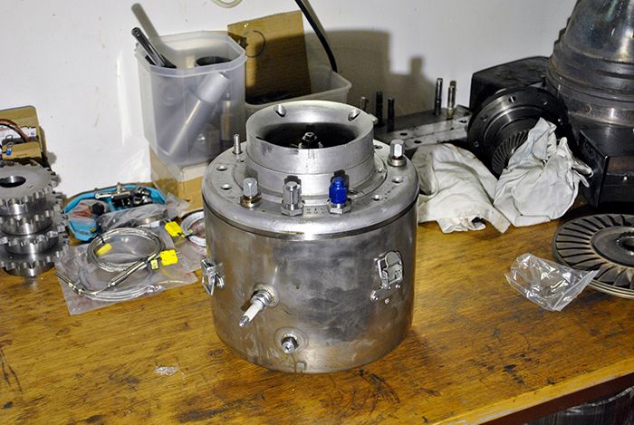 The probes and the temp displays arrived a few days ago so time to get busy! 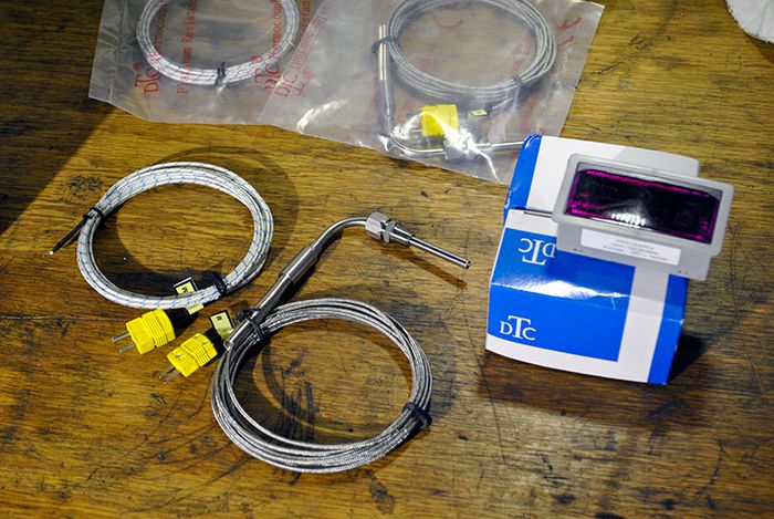 I drilled a 5mm hole in the compressor cover between two diffusor slots, it is the smaller one right next to one of the fastening bolts for the cover. 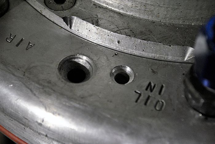 A small brass sleeve was made and the temp probe was glued to it with epoxy, the sleeve fits the hole and will be locked in place with a strip of metal held by the fastening bolt for the cover. 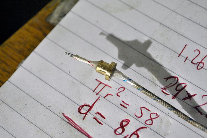 While waiting for the glue to set I fitted the TIT probe, it projects through a hole in the combustor downstream the teritary holes. 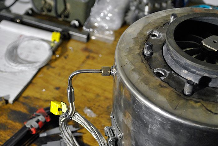 Cheers! /Anders |
|
|
|
Post by Johansson on Sept 24, 2014 13:51:29 GMT -5
After fixing some air leaks I put the engine back together and fitted it into the frame again, here is your truly posing with a screwdriver while taking a picture with his left hand. 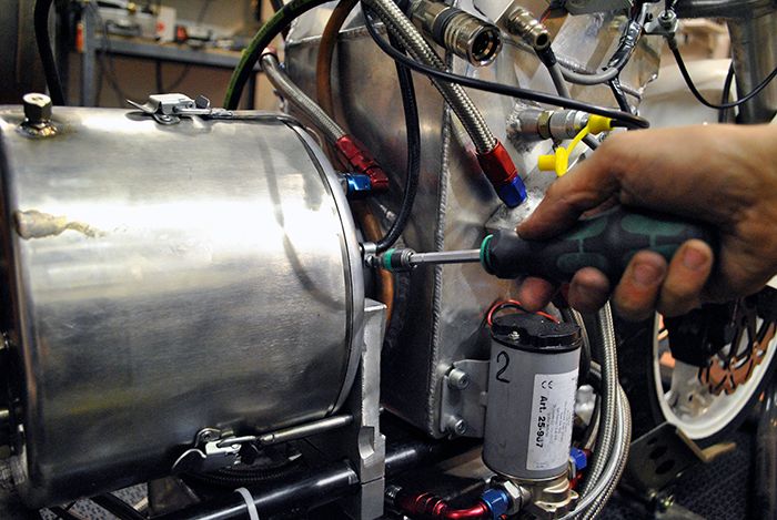 After the posing I welded the old jet nozzle to the exhaust pipe. 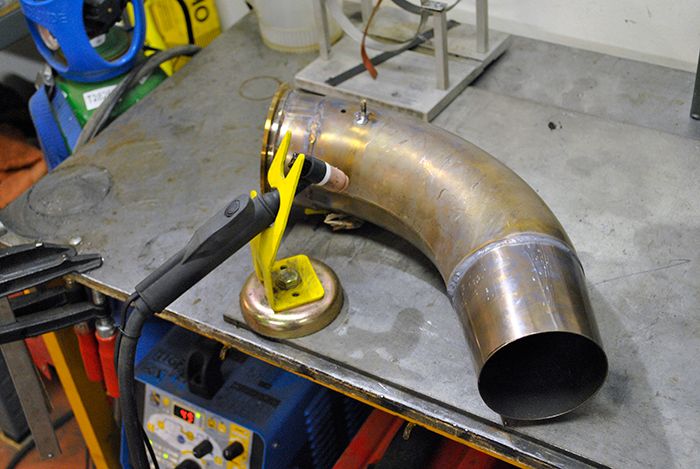 When it had cooled down a bit I fitted it to the engine, this jet nozzle has produced a 740°C TOT at 2.6bar P2 so now I have some numbers to compare the upcoming test results with. 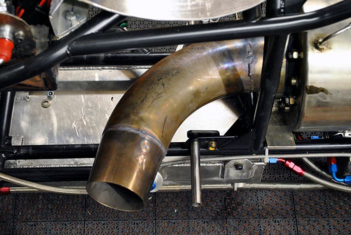 With the engine in the frame I could fit the temp probes without risking to break them. 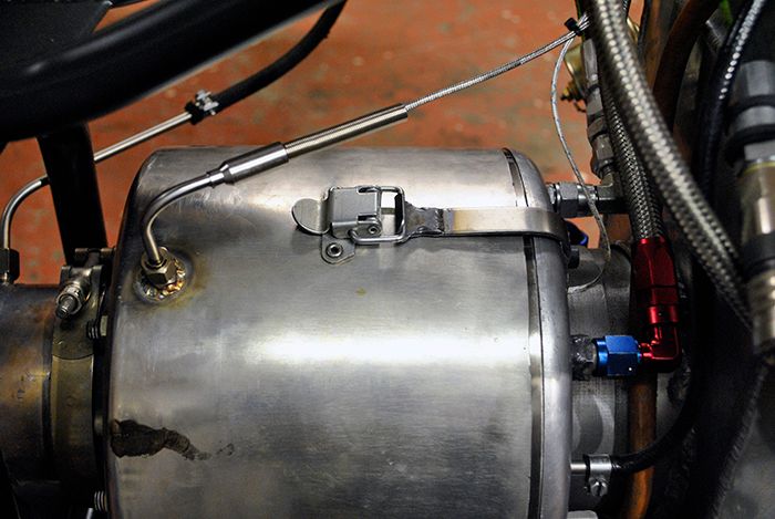 Finally I fitted the digital gauges to the dashboard and hooked them up, if they work fine I will get a couple more since they were very cheap compared to the analogue exhaust temp gauge I use to read the TOT. 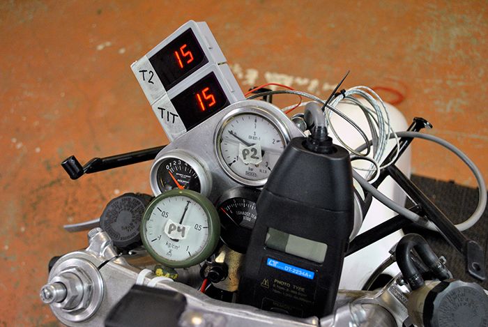 Cheers! /Anders |
|
|
|
Post by ernie wrenn on Sept 24, 2014 14:11:18 GMT -5
Time for a new dash. Probably get 5 mph just reducing air drag.. Mount go pro on your helmet.
ernie
|
|
|
|
Post by Johansson on Sept 24, 2014 14:31:47 GMT -5
This is only temporary, the dashboard will only hold the gauges absolutely necessary for running the engine. All the other stuff I will make a data logger for so I can compare the curves after each run, no need for the rider to see anything else than oil pressure, P2 and exhaust temp.
|
|
|
|
Post by Johansson on Oct 5, 2014 11:10:43 GMT -5
I did the gas producer test today, the added jet nozzle made the exhaust temps even higher so I didn´t press the engine overly much. 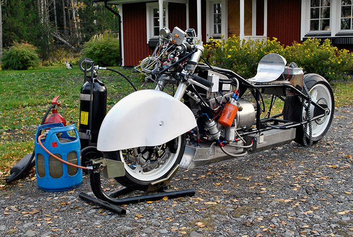 The T2 gauge interfered with the camera somehow causing the numbers to roll over the display, but they can still be seen fortunately. I have started on an Excel sheet where I enter all the data from each run so I have a couple of hours of work with that ahead of me. I will also punch some numbers to find out if the T2 is in the ball park, my gut feeling is that if I open up the exhaust a bit the engine is just fine. If I want to have the bike ready for the race in february I need to find the quick fix and get the bike up and running, and right now I think that opening up the power turbine NGV a bit will make the exhaust temps drop to acceptable levels. Finding that last ounce of power in the engine can be done later, now I want to get it ready for the race track! Cheers! /Anders |
|
|
|
Post by Johansson on Oct 5, 2014 14:04:19 GMT -5
I tried my best to sort out some numbers from the video, damn me for not slowly increasing the revs from idle to full throttle like I had planned. As usual common sense disappears as soon as a gas turbine is started... 34.000rpm 0.25bar P2 0.08bar P4 790°C TOT 54°C T2 ---------------- 42.500rpm 0.8bar P2 0.13bar P4 750°C TOT 81°C T2 ---------------- 54.500rpm 1.4bar P2 0.3bar P4 750°C TOT 130°C T2 ---------------- 60.500rpm 2.0bar P2 0.48bar P4 760°C TOT 159°C T2 ---------------- 63.500rpm 2.2bar P2 0.55bar P4 780°C TOT 174°C T2 ---------------- |
|
|
|
Post by racket on Oct 5, 2014 17:15:06 GMT -5
Hi Anders
Numbers ......I love numbers :-)
Lets look at the 63,500 rpm .
3.2 PR , if a 15 deg C day then the comp is only working at a rather poor 71% effic if T2 is 174 C ( 159 C rise) , this will require an ~137 deg C drop thru the turb
T I T will be 780 + 137 +273 = 1190 K or an acceptable 917 deg C , assuming 80% turb effic then there'll be a need for a 1.79 PR across the turb
If theres a 5% drop thru the combustor we have a 3.04 PR going into the turb , we divide by our 1.79 PR to give us a theoretical PR of 1.69 in the jetpipe , you measured a 1.55 PR , not really close enough :-(
Anyway , using the 1.55 PR at 780 +273 = 1053 K , we'd have a temp drop of ~103 C degrees thru the 95% effic nozzle giving us a velocity of ~1,600 ft/sec , density at the nozzle at ~950 K is 43 cu ft/lb . or a mass flow near 2.5 lbs/sec for ~ 125 lbs of thrust.
Theres a couple of things I see need checking , firstly the T2 is too high for the P2 ( assuming a 15 C day ) and secondly the jetpipe pressure is "too low" for the T I T temperature being used, it sorta points to the compressor not working efficiently enough, efficiency should be closer to 75% at that PR .
LOL............you might need to fire her up again and take things slower so temps have time to stabalise , try and hold the RPM at the same level as the lines on the comp map so that its easier to cross reference .
She spooled up nicely , no dramas there , you've got that all sorted :-)
Temps at high rpm are "acceptable " its those lower rpm ones that are of concern still ( rule out your freepower stage as the problem) just can't quite understand why , at 42K you had 0.13 bar of "backpressure" whilst at 63K you had 0.55 bar but only 30 degrees hotter ...........I might have to think on this one :-(
Cheers
John
|
|
gidge348
Senior Member
Joined: September 2010
Posts: 426 
|
Post by gidge348 on Oct 5, 2014 19:39:38 GMT -5
.............., it sorta points to the compressor not working efficiently enough, efficiency should be closer to 75% at that PR ............. Just looking at this for the outside, I am still wondering if it could be some problem with the intake box. Is it worth re-running the test with the air-box removed to see if there is any difference? At least this would be a reasonably easy thing to rule in or out? |
|
|
|
Post by smithy1 on Oct 5, 2014 20:26:08 GMT -5
.............., it sorta points to the compressor not working efficiently enough, efficiency should be closer to 75% at that PR ............. Just looking at this for the outside, I am still wondering if it could be some problem with the intake box. Is it worth re-running the test with the air-box removed to see if there is any difference? At least this would be a reasonably easy thing to rule in or out? Gidge, I think Anders did some "P1" tests some time ago and there was no noticeable difference with the airbox on....although the pressure readings don't give any indication of airflow irregularities which may be happening. I wonder if fitting some airflow "streamers" or "smokers" would help indicate if the air is doing anything strange prior to going into the comp inducer. Anders, Is there a way you could measure your compressor tip/profile clearances? If they're excessive it may point to an issue. As John mentions, your compressor "should" be a little more efficient than the numbers would indicate. Cheers, Smithy. |
|
|
|
Post by racket on Oct 5, 2014 20:29:13 GMT -5
Yep , the comp numbers aren't real good , theres something strange going on, though having said that, some are "closer" to whats expected ............abberant inlet air flows ??
I just checked some vid of my 10/98 engine and with the same 89mm jet nozzle I had T O Ts of 540 C at 36,000 rpm , 520 C at 45 K , 550 C at 55K and 570 C at 60 K , the usual bit warmer at lowish rpm where the rotative is a bit inefficient ,then cooler as efficiencies go up with rpm , then a gentle temperature climb as backpressure increases as the rpm climb.
Cheers
John
|
|
|
|
Post by Johansson on Oct 5, 2014 23:14:09 GMT -5
Hi guys,
The high idle temps really confuse me, and if I had made a better test run with slow throttle increases the numbers would have been easier to read.
Thanks for the calcs John, it is strange that the P4 won´t add up with how the engine is running. Could it be the large NGV throat that is causing this?
Running the engine without the air box is almost impossible, I would have to completely rebuild the whole bike since every hose and fitting going to the engine comes from something bolted to the air box.
The comp tip clearance might be worth investigating, I know for sure that it is on the large side since I deliberately chose a larger clearance early in the test process when the comp wheel rubbed the housing after one of the overly long preheat cycles. I will check it and get back to you.
What should the next step in the testing be? I want to check the syringe needles for blocking/leaks, and I can decrease the compressor tip clearance a bit (easy to do since I use shims) to find out if that is what is causing the problem. Other than that I am at a loss, I have inspected the engine internals and I cannot see any heat damage in the combustor or anything else that indicates a problem.
Cheers!
/Anders
|
|


