|
|
Post by racket on Jul 10, 2014 15:49:18 GMT -5
Hi Patty
Weld them on
Cheers
John
|
|
|
|
Post by madpatty on Jul 13, 2014 14:01:09 GMT -5
I had been playing with some CFD on the basic layout of the combustion chamber of my engine....    As i am a beginner with all this stuff, so i wasn't able to fully decode the results.... Don't know how much right they are!!! Anybody any thoughts, please share.... cheers, Patty |
|
|
|
Post by madpatty on Jul 13, 2014 14:05:18 GMT -5
In the lower most picture,
The area in RED is the Turbine Inlet.
The area in BLACK are the flametube walls.
Air enters from above(Circular periphery).
cheers,
Patty
|
|
wolfdragon
Senior Member

Joined: April 2011
Posts: 287
|
Post by wolfdragon on Jul 15, 2014 15:29:10 GMT -5
It doesn't look like the CFD understands the flow needs to go into the turbine inlet...
|
|
|
|
Post by madpatty on Jul 15, 2014 21:06:21 GMT -5
Ok Wolfdragon,
Maybe some wrong boundary conditions at the turbine inlet....
I set that to mass outflow..had to experiment with other conditions or you suggest any...
Cheers,
Patty
|
|
|
|
Post by madpatty on Jul 16, 2014 22:17:23 GMT -5
Hi Racket, The CFD analysis shows max. Air velocity of around 130-150 ms-1 in the centre of primary and secondary zone and a bit higher 170 ms-1 in the tertiary zone inside the annular flametube... How about the above figures? 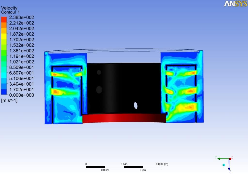 Thanks, Patty |
|
|
|
Post by racket on Jul 16, 2014 23:27:42 GMT -5
Hi Patty
LOL.........I wouldn't have the faintest idea whether those velocities are good or bad ...............I just make them , I don't design them , .......if they look right to me , then thats good enough :-)
Cheers
John
|
|
ashpowers
Veteran Member
Joined: February 2011
Posts: 207
|
Post by ashpowers on Jul 17, 2014 10:00:25 GMT -5
I would be looking at the burn rate of vaporized kerosene per distance at your given pressure ratio. It looks to me like you have too much high velocity air in the primary zone and too little of the low velocity volume to support good combustion.
|
|
|
|
Post by madpatty on Jul 17, 2014 13:57:15 GMT -5
Hi Ashpowers,
so what according to you are the permissible range of velocity in primary zone for good combustion....
because i have already kept everything including, diffuser diameter and flamtetube diameters large than normal so as to lower the air velocity.
Thanks,
Patty
|
|
rythmnbls
Veteran Member
Joined: August 2011
Posts: 145
|
Post by rythmnbls on Jul 17, 2014 14:56:10 GMT -5
Hi Ashpowers, so what according to you are the permissible range of velocity in primary zone for good combustion.... because i have already kept everything including, diffuser diameter and flamtetube diameters large than normal so as to lower the air velocity. Thanks, Patty Read this post, this should give you an idea of the air velocities you should aim for. jetandturbineowners.proboards.com/post/8741/threadRegards. Steve |
|
|
|
Post by finiteparts on Jul 17, 2014 20:05:24 GMT -5
Hey Patty,
I would suggest that you don't get too hung up with the CFD values. Non-reacting CFD is a good tool to get an estimate of where the air may go, but it is REALLY, REALLY hard to get an accurate prediction of what will actually occur when a reacting flow is introduced into the chamber...once a flame is introduced in the chamber, the flow-field changes due to the variable gas densities throughout the combustion process.
The values that I stated in the post cited by Ash were for illustration of how flow velocity impacts the fundamental pressure loss due to heat addition in a tube...I wouldn't say that they have any merit as design values. Turbulent flame speeds for kerosene measure under 4 m/s, so you need to make sure that the flame anchoring point has a region where the local velocity is below this, otherwise you will blow the flame out. But the bulk flow speed in the rest of the combustor may be higher once the flame has found a stable anchor point.
What you can get of value from your work is that the dilution jets appear to plunge well into the main flow and thus should create good mixing in the chamber. It also looks like you might have a preferential air feed to the outer dilution holes, because these jets are much stronger than the jets from the inner liner. This may be ok or it could cause you to have some high metal temperatures in the inner liner since the flame may be more mixed out closer to the inner liner (this is only a speculation...combustion is REALLY hard to predict).
The important points in designing the length and flow velocities in the combustor are more related to the chemical reaction rates, which this CFD will not capture. Even the high end reacting flow-large eddie simulation CFD have a hard time capturing this accurately due to the high complexity of the problems involved. When doing the combustor design for Senior Design project in college, I used Jack Mattingly's book "Aircraft Engine Design", which came with a simplified chemical reactor modeling program called KINETX, written by Dr. David Pratt. The program allows the user to model the combustor as a series of idealized reactor models, ie. "well-stirred", "plug-flow", and mixing and recycling elements. For my project, I used the Bragg combustor model in which the primary zone is modeled as a well-stirred reactor followed by a plug flow reactor for the secondary zone...the tertiary zone was not modeled. The output gives you estimations of the residence time, regional equivalence ratio/temperature and combustion efficiency among others. It is easy to use, but hard to interpret due to the book using different variables than the software. I used it to check the sizing of the combustor zones for complete combustion and my combustor did work well, but I also used may of the rule given in Lefebvre's "Gas Turbine Combustion" book, so I was not expecting to be too far off in design space.
So where are your injectors in this design?
~ Chris
|
|
|
|
Post by madpatty on Jul 17, 2014 21:11:53 GMT -5
Hi Chris,
Thanks for sharing the information...
I was just trying to predict te cold flow properties of te combustor as yet...
The injectors(actually evaporators) will be placed with their openings near the inner wall of flametube in primary zone....that region is showing the minimum values for velocity...
Cheers,
Patty
|
|
|
|
Post by madpatty on Jul 18, 2014 10:54:28 GMT -5
Hi Racket and anybody who can answer,
I have a problem routing the lube oil inlet and outlet in such a tight space....inner flametube is already 50mm in length so cant really make it anymore shorter....
Steel pipe i tried to bend them but they get cracked as soon as some curvature begins to form...
I know this has got variable answers but if anyone can share some pics or experiences so that i can gather an idea or two if possible...
Thanks,
Patty
|
|
nersut
Veteran Member
Joined: September 2012
Posts: 223
|
Post by nersut on Jul 18, 2014 12:03:51 GMT -5
Hi Patty Try with annealed copper or steel tubing instead. Easily bend with simple tools. Please read this first. Copper tubing under soft copper and this Annealing.
Cheers Erik |
|
|
|
Post by madpatty on Jul 19, 2014 10:36:38 GMT -5
|
|


