|
|
Post by finiteparts on Sept 24, 2014 0:57:32 GMT -5
Oh, I see...and I agree.
It appears from the discussion in the papers that the discharge velocity at a PR of 9:1 would need quite a bit of length to reduce the speed to subsonic and due to the high velocity, there will be a high shear rate in the vaneless section causing high scrubbing losses, which I guess we have to assume are higher than the losses taken across a shock (or several!).
~ Chris
|
|
|
|
Post by racket on Sept 24, 2014 4:17:11 GMT -5
Hi Chris
The ploy with turbochargers is to have a reducing vaneless space height outboard of the comp wheel , this forces the air to a greater radius quicker reducing losses , whilst the quicker increase in radius hastens the diffusion process .....I used a similar setup on my FM-1 engine where my vaneless space was a good half inch wide , I felt the extra width could be an advantage for a motorcycle turbine engine which would be subjected to frequent and fast throttle changes .
Turbo comp wheels in general are crappy gas turbine wheels due to the high Trim numbers which are an asset for a turbo where it reduces the moment of inertia , but it means inlet problems at lower pressure ratios than if we could use low Trim wheels , most turbo comps are in the 52-56 Trim range whereas gas turbines would prefer something in the sub 50 range , preferably down near 40 Trim to reduce those inlet relative velocities and improve efficiency.
Cheers
John
|
|
|
|
Post by finiteparts on Oct 23, 2014 19:41:37 GMT -5
|
|
|
|
Post by racket on Oct 23, 2014 22:25:42 GMT -5
Hi Chris
Sweet :-)
Our TV94 based engines have roughly the same output as the Rover , and it was doing 140 mph in its day .
Thanks for the Link
Cheers
John
|
|
|
|
Post by finiteparts on Nov 11, 2014 16:46:13 GMT -5
|
|
|
|
Post by finiteparts on Nov 22, 2014 15:53:04 GMT -5
This post is directed at a question asked here, jetandturbineowners.proboards.com/post/10739For your purposes, there should not be much difference in engine performance based on which one of those turbines you choose, but if you have the chance to get either or, I would choose the turbine with the rake on the inlet blade. The general rule of thumb for radial turbomachinery is that when you see "rake" applied to the inlet of a turbine or the outlet of a compressor wheel, it is there in an effort to modify the blade loading so as to minimize losses from secondary flows in the blade passage. The blade loading is essentially the pressure difference across the blade surface, from the one side of the blade to the other side. One side will have a higher pressure than the other side in order to create a net force (think of lift on an aircraft wing). The lower pressure surface is termed the "suction" surface and the higher pressure surface is termed the "pressure" surface. The difference between them gives the amount of force created. So in the figure below,the curves essential show the static pressure on the surface (Cp is the pressure coefficient, which is a normalized version of the static pressure).  You can see that the upper surface is the "suction" surface since it is lower pressure (note the values on the y-axis are reversed to make is more easy to see relative to the airfoil) and the lower surface would be the "pressure" surface. If we integrate the area contained between the two pressure contours, we could calculate the lifting force that this airfoil section would produce. The dashed lines show the ideal static pressure on the airfoil surface, while the yellow and blue lines represent the effect of the boundary layer growth. Since the boundary layer dissipates some of the free stream energy by momentum exchange to the stagnate fluid close to the surface, which is a loss, we can see that the area between the curves over most of the profile is reduced and thus the ideal lift of the airfoil is not achievable. This is what blade loading is all about. If we increase the blade loading, the lift that each blade must provide increases. To do this, the curves would have to move apart. Notice that the suction surface is only accelerating the flow at the leading edge and it is a sharp acceleration (the pressure is falling and thus the yellow line is increasing)....for the rest of the travel over the upper surface, the flow is decelerating or in terms relative to the surface static pressure, "diffusing". As long as the flow doesn't seperate, the losses are fairly small, but when it does, the flow losses jump up which means here that the drag jumps up and you waste propulsion power trying to over come the extra drag...for our turbomachinery, the work that we can put in to or pull from the mean flow is reduced. On the plot, you can see separation "bubbles" on the upper and lower surface just past the 75% chord area. When we get separation in our turbomachinery systems, we will not likely get the flow to reattach due to the other multitude of forces acting on the fluid and they will usually grow as the flow progresses through the passages. The airfoil was a really simple 2-dimensional example. Once we stack blades together, we get cross-passage flows due to the fact that there is now a pressure and suction side within the same passage, so a pressure difference from one side to the other to drive the secondary flows. We also have the fluid turning some strong angles through the passages. If you watched the Nation Science Foundation (NSF) Secondary Flows video that I posted above, you will remember that streamline curvature can only occur due to a streamline normal pressure gradient which is strongly dependent on the radius of curvature and fluid velocity. What this means is that the flows in our turbines or compressors are really complicated! So, back to the rake on the turbine blade inlets. Back in the 1980s, there was a need to reduce the lag time of the turbos when the driver stomped on the accelerator. This is still a big deal since the turbine wheel usually accounts for up to 80% of the assembled turbocharger rotor's polar moment of inertia! Borg Warner has even gone as far as making the turbines out of the super light but super expensive titanium aluminide, (TiAl). But back then, they had heavy Inconel (though they were working on lighter ceramics) and so other things had to be done. The physical parameter that defines a bodies resistance to move when a force is applied is it's inertia and for a rotating body, it's rotational inertia is dependent on what is termed it's polar moment of inertia. The polar moment of inertia is driven in a simple sense by the amount of material and the distance that material is from the rotational axis. So, to minimize the polar moment of inertia, you try to reduce the amount of material that is farther away from the rotational axis. Thus the scalloping of the material between the blades at the back-face of a turbine rotor. Other things such as thinner blades, smaller blade diameters, etc can also be applied to try to reduce the mass-distance effect, each with a trade-off in performance or durability. The one thing that many turbo manufacturers have done is to reduce the blade count, which had a minimal if not positive effect on durability and producability. But, the big thing that reduce blade count does effect is to increase the blade loading. With the increased blade loading each blade has to produce more power for the same amount of gas flow, thus the pressure difference between the suction sides and pressure sides has to get larger like we saw above. Compressors get away with this by adding splitter blades, but splitter blades have not been successful in the past for turbines. Nissan Motor Co. put out a good paper on their work in the 1981 time frame that was presented at the 1982 IMechE conference on Turbocharging and Turbochargers... titled, "Reduction in the polar moment of inertia of an automotive turbocharger by controlling aerodynamic blade loading", (F. Nishiguchi, Y. Sumi and K. Yamane). If you can find it, it is definitely worth a read. They reduced an 11 blade turbine down to a 9 blade with essentially no change in the performance (~ 80.5% efficiency) by controlling the secondary flow losses in the turbine passages with the addition of blade rake to the inlet. An interesting point is that the moment of inertia due to the blades only was approximately the same as the moment of inertia due to the disc portion of the turbine only. The main advantages of the rake was that it allowed the designers to modify the flowpath of the turbine without having to curve the blades in the radial plane...which is called non-radial stacking. By keeping the blades radially stacked, the centrifugal forces are kept inline with the blades material. If the blades bent in the radial plane, the centrifugal pull on one portion of the blade would cause a bending stress in an adjacent portion of the blade...this would increase the blade stress and reduce its durability. The second advantage was due to the aerodynamic flowpath changes which allowed an increase the inlet velocity at the pressure side-hub corner reducing it's recirculation zone, while also reducing the velocity at the shroud side which has the higher streamline curvature and thus the losses due to scrubbing, leakage, etc. Sorry for the long post, but I thought that it might be interesting to share the whole story as opposed to just saying the first line with no background...then the reader can choose to read or not depending on their desire to more thoroughly understand the underlying physics. ~ Chris |
|
|
|
Post by madpatty on Nov 22, 2014 20:35:08 GMT -5
Thanks Chris for sharing such an important piece of information.....
One thing that came to my mind when i first saw that turbine wheel was its similarity to Francis turbine....(i may be wrong also)
But now i am sure that blade curve at entry is to produce some reaction force or lift in direction of rotation of turbine wheel so as to enhance its power producing ability....
Cheers,
Patty
|
|
|
|
Post by finiteparts on Nov 22, 2014 22:52:02 GMT -5
Hi Patty,
I just want to make sure that your not thinking that it is just the shape of the tip. Adding the rake angle to the tip allows the shape of the rest of the blade passage to be modified from the inlet to the exducer, while keeping the mechanically more robust radial stacking of the blade profiles.
As for the Francis turbine, yep, it is very similar...well, assuming we are talking about similar degrees of reaction in the stage. The flow at the turbine inlet should be as near to straight into the passage as possible, there is essentially no impulse transfer at the inlet, the momentum exchange is due to the turning in the nozzle guide vanes and the exducer. One would think that this means for the design of the NGVs, the result should be that the relative inlet flow is at zero incidence to the turbine inlet at design speed, but, it turns out that you actually get peak efficiency when the relative inlet flow has an off incidence approach angle in the 20 to 40 degree range.
I will follow up this post with that information once I collect up the sources to cite. I know that Solar was one, but some other designer have also reported this for quite some time. The common theory is that due to the secondary flows, there is essentially an in passage vortex flow that either helps or hinders the formation of inlet flow separation depending on the inlet flow incidence angle...so in order to get a straight inlet flow you actually have to "offset" the velocity component of the passage vortex at the inlet by feeding the inlet with off incidence flow...I'll make a few figures to illustrate this also.
~ Chris
|
|
|
|
Post by madpatty on Nov 23, 2014 0:57:29 GMT -5
Hi Chris,
Yes i need some figures now to get a proper feeling of what happens at turbine inlet.....maybe a velocity triangle with all those off-incidence angles will make it clear to me properly.....
one thing that is confusing me now is that i always used to think that maximum impuse tranfer is occuring at turbine inlet due to those flat blades at turbine inlet and maximum reaction force occurs at exducer due to that curved shape of blades at turbine exducer.....
just correct me if am wrong
Thanks.
Cheers,
Patty
|
|
|
|
Post by finiteparts on Nov 23, 2014 20:58:21 GMT -5
Hi Patty, I found a nice online resource to show you what I was referring to...it is Glassman's Turbine Design on NASA's report server here: ntrs.nasa.gov/search.jsp?R=19750016669So, for our discussion, the relative inlet flow angle, beta 1 is shown in the vector triangles on page 35. On the next page, there is an illustration of the flow entering the turbine. You can see that the relative flow once in the turbine passage is essentially straight...and as Rohlik states, "Note that the flow at the stagnation point is approximately radial. If this were not so, the flow would tend to separate from the suction surface near the leading edge, causing excessive loss." The equation suggested in the report has been updated and reported by Whitfield and Baines - "Design of Radial Turbomachines", to be more accurate when using, cos(beta 1) = 1 - ( (0.63* pi) / Zb ) where Zb is the number of blades So the above equation gives an optimal relative flow angle around 36 degrees of negative incidence for my 10 bladed S475 Borg Warner turbine. This seems in the ball park of what has been reported in the literature. A few examples include: Rodgers, 1987, "Mainline preformance predictions for radial inflow turbines" - reported peak efficiency around -20 degrees Rohlik, 1975, "Radial inflow turbines" (Link given above) - reported peak efficiency at angles up to -40 degrees Yeo & Baines, 1990, "Pulsating flow behavior in a twin entry vaneless radial inflow turbine" - reported at angles of -25 degrees Jones, AC, 1996, "Design and test of a small high pressure ratio radial turbine" - reported an angle of 31.5 degrees on the Solar T100 engine. Since these reports did not mention the blade counts, I cannot check these test results based on the above equation, but the first three sources should have been included in the data that Whitfield and Baines used to modify the equation. Remember that this is due to the static pressure gradient that exists in the flow passages of the turbine rotor. The higher static pressure on the pressure surface means that the bulk flow speed is reduced and thus the bulk flow tends to go to the higher speed/lower pressure suction surface. This can also be modeled by applying Coriolis acceleration in the rotating passages, which gives an in passage vortex counter rotating relative to the rotor rotation. (Remember that Coriolis acceleration is the reason that water drains in one direction in the northern hemisphere and the other direction in the southern hemisphere.) The in passage vortex, that tends to turn the incoming flow inward is shown below. You can see how it would reduce the flow speed on the pressure side (PS) and increase the flow speed on the suction surface (SS)... 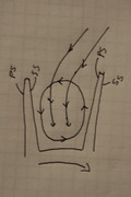 So, with that in passage vortex in mind, here is a sketch of the flow visualization from Wooley and Hatton, 1973 on the effect of inlet flow incidence, 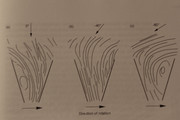 Finally, the concept of using impulse at the tip for our turbocharger turbines is totally incorrect. If there was enough off-incidence flow to create an impulse, there would be a large flow separation at the inlet and the turbine efficiency would suffer. If you look at page 51, figure 10-19a, you will see a "familiar" plot of surface conditions (modeled, not measured). This one is in terms of flow speed, but remember that higher surface velocity means lower static pressure and vice versa for the low speed flows...so it is essentially the same sort of plot as the airfoil static pressure plot, but some mental conversion is necessary. So, with that in mind, you can see that there exists a pressure difference that produces the force on each blade, which produces a torque around the shaft centerline. The point is, the blade is essentially an "airfoil" producing a reaction force. You can see the strong cross passage flow differences at the inlet (even if they are artificially high due to the model, page 52, figure 10-20 is probably more realistic at the entry stagnation point) , the pressure side is a negative velocity (reversed flow, thus a region of flow separation), while the suction surface is well above the inlet free stream velocity. This should give you a good idea of why clearances between the turbine and the housing are important. I hope that helps. ~ Chris |
|
|
|
Post by finiteparts on Dec 8, 2014 23:58:47 GMT -5
It is always interesting where the reference section of papers takes you...commonly cited reports on centrifugal compressor losses led me to two very interesting papers. The first shows early work (1945) on understanding the flow structure on surging compressors (back-flow). Two good take-aways from this paper are the use of lampblack to "visualize" the reverse flow in the boundary layer and the use of tufts to visualize the compressor entry flow stability. Figure 7 gives a great visual of how the shroud flow can break-down and "back-flow" towards the inlet....this is also commonly seen in vaneless diffusers. Later work discovered that if there was a bleed slot strategically placed near this region, the back-flow could essentially take a short-circuited path back to the compressor inlet (out the bleed slot, through the bleed port and then back into the inducer) thus not causing the large, shroud-flow separations in the inducer that would otherwise occur and aggravate the stability problems. ntrs.nasa.gov/archive/nasa/casi.ntrs.nasa.gov/19930091885.pdfThe second excellent paper is given in this reference: ntrs.nasa.gov/archive/nasa/casi.ntrs.nasa.gov/19750003102.pdfThe paper is on page 301, "Boundary Layers in Centrifugal Compressors" by Robert Dean, Jr. If you read much of the work on centrifugal compressors, that name will sound very familiar to you because Dean, while working with Creare Inc., did a lot of research on high pressure ratio centrifugal compressors. I feel that this paper really does an excellent job giving the reader a better insight into some of the boundary layer affected flow physics than some of the other sources out there. It does have to be remembered that often he is talking about very high pressure ratio compressors, so it may not be as relevant for our low pressure machines, but I highly recommend this paper anyway. The discussion on the flow control of the diffuser on page 308 (in reference to figure 5, shown below) is pretty interesting...Upstream of the shocks, the lines of constant static pressure (isobars) are increasing radially outward as one would expect, but right after the throat, the isobars have rotated and the flow is behaving just like a one-dimensional diffuser. 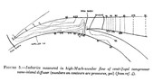 Enjoy! Chris |
|
|
|
Post by finiteparts on Dec 19, 2014 22:19:39 GMT -5
Just in case some of the engine designers out there are not to proficient with the differences between static and total (also called stagnation) flow conditions or are using a Bernoulli's equation with constant density (incompressible flow approximation) to calculate the highly compressible flows in turbine engines, I found a link to a pdf version of Saad's Compressible Flow book that might come in handy... Sorry...the link was deleted due to the original page being pulled down....Start around page 19 where he describes the stagnation properties, this will give you the information on why you need to use the static or stagnation and the equations which are based on the flow velocities...then jump to page 87, where he gives you a equation for the temperature ratio based on the local Mach number...then from the other "isentropic relations" you can find the static or stagnation (also called total, I use them interchangeably) pressure and density...notice that the isentropic relations occur under the assumption that there is no entropy change ("isentropic" = same disorder), which is not realistic since there are all kinds of flow generated losses within the engine, but it is a better start than assuming that the gas goes through the engine at a constant density. At low Mach numbers (M < 0.3) you can sort of ignore the changes in the gas density, but as the Mach number is increased, compressible effects become more significant and you will get larger calculation errors. So, if you are designing a diffuser or a nozzle guide vane section, you will have to consider the static conditions to get the local density, while likely starting from the stagnation conditions. Additionally, the values on the compressor or turbine maps assume you are selecting the correct thermodynamic state...notice that the compressor pressure ratio and efficiency are based on total to total, while the turbine flow capacity is based on the total to static pressure ratio...so if you had the compressor efficiency calculation based on static temperatures, you would get an incorrect value. The compressor pressure ratio is based on total to total values, so if you want to determine the static pressure available at the combustor (say for example: to calculate the flow rate through the dilutions holes based on static pressure drop charts in many of the publications), you would need to know the velocity of the air so that you could calculate the static pressure from the total pressure. 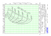 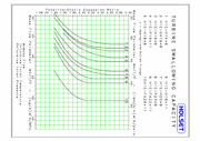 The above examples may not be so critical since the flow velocities are lower, but say you are assuming the NGV discharge pressure is the same as the combustor pressure (essentially the total pressure), that will get you a throat section that is incorrectly sized for the local gas flow that is sensing the static gas pressure (or more accurately, the local gas temperature), especially if you are trying to design the NGV to choke at a certain mass flow. So in the compressor and the turbine maps above, why doesn't the description of the inlet pressure or temperature specify static or total? The reason is that the usual convention is to assume that the inlet condition is feeding from a large plenum, thus at some distance from the inlet the flow speed is very small, nearly zero. At zero flow speed, the total and static temps, pressure, etc are equal. Enjoy! Chris |
|
|
|
Post by finiteparts on Dec 19, 2014 23:59:21 GMT -5
So I was talking with Patty about selecting the NGV throat area and thought that this might be a good post, since I am not sure how others are doing this, but it is relatively straight forward calculation that should not be confusing....unfortunately, it seems that people like to give lots of responses with their numbers, but without seeing the calculations, how do those out there that are new to the process learn? I had a Classical Mechanics professor in my undergrad work that never gave out the solutions to show how to solve the problems, just the correct answer. There are problems that I worked on for days that I couldn't get. I would meet with him and he would suggest some obscure mathematical relation that would allow me to solve it. Sometimes, you know the basics, but you just need to see the process or the trick. So here is how I worked it out... 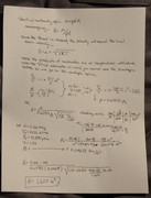 The throat can be located on a drawing or an actual part by drawing a circle that fills the nozzle exit and drawing a line between the two tangent points. 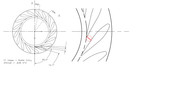 Another point on the design of NGVs. If you have a larger amount of tangential velocity (swirl) at the entrance of the NGVs, like a scroll housing would produce, then the NGVs don't have to turn the flow much and flat vanes might be ok (similar to what is shown above)...but, if the flow is entering from an annular combustor in which you are not producing any significant swirl, you need to have the vanes radially oriented at the entrance as show below... 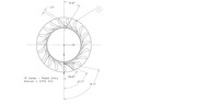 so the vanes smoothly capture the flow and then turn it into the rotor. If you had flat plate style NGVs with a radial inflow gas entry, you could develop large flow separations and thus a large blockage at the throat, making your carefully designed throat, undersized and choking early. Additionally, the flat plates make it harder to adjust to get the proper throat area. I have seen comments on here about setting the vane angle so that the throat area is reached based on the angle only. That is absolutely incorrect. You need to do the vector calculations so that your flow angles are set correctly based on the rotor design point operating condition. The throat area required is based on the mass flow and entry conditions. The throat area can be adjusted by thickening the vanes, putting in more vanes, but not by randomly changing the vane discharge angle around. Remember, the NGVs are swallowing some of the highest velocity air in the engine. Taking shortcuts on the build here will impact the engine performance drastically and thus you should really work as hard as you can to make them as good as you can. I hope this helps! ~ Chris |
|
|
|
Post by finiteparts on Dec 20, 2014 1:03:30 GMT -5
A quick follow up point to the above calculations...the calculated area is the required effective area...so the required geometric area will be larger depending on the discharge coefficient of the passages. Recall, that the effective area is,
Aeff = Cd * Ageometric
Make sure to adjust for welds in the corners reducing flow area. Also, the cold dimensions change due to the hot gas flow and the metal thermal expansion, so the hot condition may be a few percent or so larger. It is easy to check, if you are going for high build accuracy.
~ Chris
|
|
|
|
Post by finiteparts on Dec 20, 2014 2:29:06 GMT -5
Whoops! I found a copying error from when I ran the calculation previously with an inlet pressure of 35 psia, then forgot to update it to the pressure that Patty was targeting...
So...Change the stagnation density equation, to show the stated inlet stagnation pressure of 41.9 psia...this gives a density of 0.05593 lbm/ft^3...then substituting that into the effective area equation gives a slightly smaller throat area of 1.364 in^2.
I was trying to double check the number in one of my programs and it just wouldn't line up...then I noticed the two different pressures on the sheet.
Now, since my program has all this already set up, if you account for the fuel flow required to get to the turbine inlet temp of 850 C, you need to slightly increase the throat effective area up to 1.41 in^2 to handle the choke flow at the above conditions.
~ Chris
|
|


