|
|
Post by Johansson on Jan 21, 2017 15:58:15 GMT -5
I removed the can today and everything is warp-free, great! 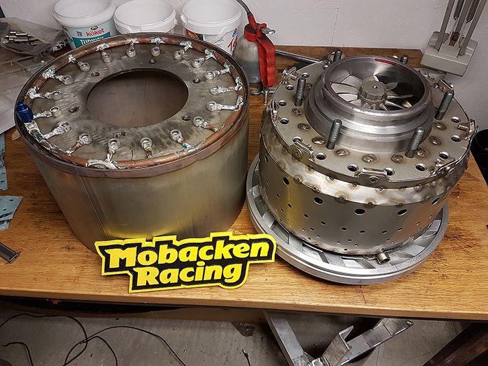 I also made a list of the jobs left to do before the engine is ready for a test run, many minor jobs like soldering the injector needles but also a fair amount of larger jobs like the starter motor and the test stand so I think I will have my hands full to get it assembled before the end of 2017. If it takes another year I don´t mind, I want to do this build properly since JU-02 feels like the power source I will use for years to come.  Cheers! /Anders |
|
|
|
Post by racket on Jan 21, 2017 16:53:09 GMT -5
Hi Anders
Looking at your pic there I feel you may have sufficient material in the comp front cover to fit your securing screws for the outer can, especially if you place then over the diffuser vanes where a clearance hole can be opened up in their outer edge for the screw to project into , with 15 X 6 mm screws it should hold as the screws are in sheer, not tension , on my FM-1 engine the outer can screws were fitted into rear projections on the diffuser vanes which allowed the front cover to be removed without requiring the outer can to be removed .
Cheers
John
|
|
|
|
Post by Johansson on Jan 21, 2017 17:07:29 GMT -5
Hi Anders Looking at your pic there I feel you may have sufficient material in the comp front cover to fit your securing screws for the outer can, especially if you place then over the diffuser vanes where a clearance hole can be opened up in their outer edge for the screw to project into , with 15 X 6 mm screws it should hold as the screws are in sheer, not tension , on my FM-1 engine the outer can screws were fitted into rear projections on the diffuser vanes which allowed the front cover to be removed without requiring the outer can to be removed . Cheers John You are absolutely right John, I totally forgot about the diffuser wedges when I checked the thickness of the material in the compressor cover. If I place the screws there I can drill the holes through and get 10-12mm of thread in there which would be plenty enough. Sweet! Anyone experienced with kero starters by the way? I am trying to decide where to place the glow plug in relation to the combustor and so far on top of the engine pointing down between two of the evaporator exits is my best guess so far. I´ll fuel it with propane to save me the trouble of having a separate kero supply just for preheating, but regardless of the fuel type the placement should be the same. Cheers! /Anders |
|
|
|
Post by racket on Jan 21, 2017 17:16:57 GMT -5
Hi Anders
Maybe at 10 or 2 o'clock so that the flame can dribble further down the can rather than onto the inner wall if at 12 0'clock , it'll also feed more evap outlets .
Cheers
John
|
|
|
|
Post by Johansson on Jan 21, 2017 17:25:45 GMT -5
Hi Anders Maybe at 10 or 2 o'clock so that the flame can dribble further down the can rather than onto the inner wall if at 12 0'clock , it'll also feed more evap outlets . Cheers John With the starter motor spinning the inrushing air will hopefully send the flame rotating around in the chamber, the flame is more torch-like than dribbling so hopefully it will do its job. Cheers! /Anders |
|
|
|
Post by racket on Jan 22, 2017 16:20:38 GMT -5
Hi Anders
Thats a nice torch ignitor , in which case at maybe at 4 or 8 o'clock so that the flame can rise up, as gas flames like to do , through the rest of the flametube , I think I read somewhere that the full sized engines using torch igniters for their evaporator equipped engines had the ignitor in the lower parts of the engine
Cheers
John
|
|
|
|
Post by Johansson on Jan 22, 2017 16:57:40 GMT -5
Hi Anders Thats a nice torch ignitor , in which case at maybe at 4 or 8 o'clock so that the flame can rise up, as gas flames like to do , through the rest of the flametube , I think I read somewhere that the full sized engines using torch igniters for their evaporator equipped engines had the ignitor in the lower parts of the engine Cheers John Hi John, That sounds logical, I´ll fit it at 5 or 7 o´clock so it won´t stick out from the side of the engine. The gas producer will be wide enough anyway. Cheers! /Anders |
|
|
|
Post by Johansson on Jan 22, 2017 18:11:23 GMT -5
This was one of those days when I went out to the workshop with no clue how to solve a problem and a couple of hours later I walk back in having come up with a way better solution than I could dare hope for. The plan was to figure out how to build the oil return line before the evening was over. 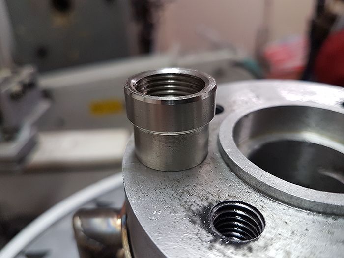 I made a threaded connection and welded it to the end of the oil return line so it would sit just inside the engine cover. 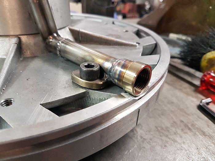 With the plasma cutter I cut a window in the engine cover and made a plate that fit the hole. 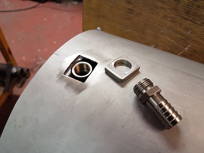 With a thin copper washer as a shim between the inner oil line and the plate I used the hose connection to screw the parts together and spot welded the plate in place. 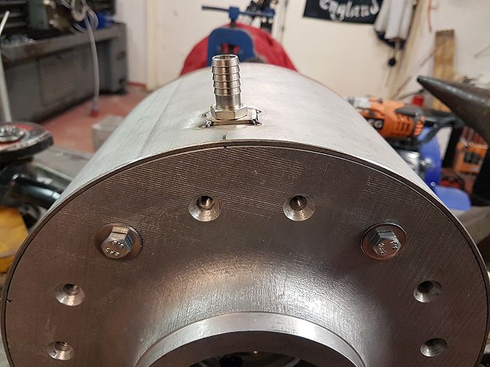 After that I welded the plate, well aware that the engine cover would warp and need some massaging with a hammer later. 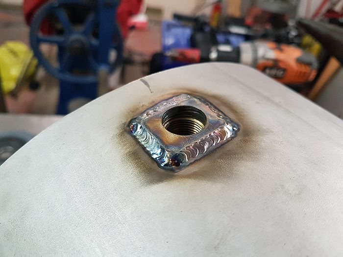 Hose connection test fitted. 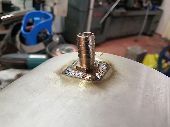 Finally I fitted the engine internals just to see how everything would line up, it turned out great so one of the more gruesome jobs was done! 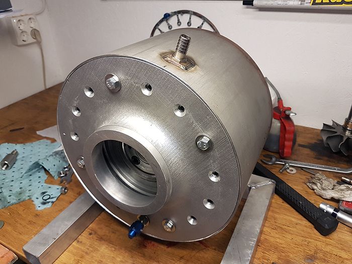 Cheers! /Anders |
|
|
|
Post by racket on Jan 22, 2017 18:45:29 GMT -5
Hi Anders
Thats a much easier solution to getting through the outer can wall than what I used on the 10/98 engine , can you use a silicone o'ring for sealing ?
Cheers
John
|
|
|
|
Post by Johansson on Jan 22, 2017 23:20:00 GMT -5
Hi Anders Thats a much easier solution to getting through the outer can wall than what I used on the 10/98 engine , can you use a silicone o'ring for sealing ? Cheers John Sure can, I´ll just drop it in there before I screw the coupling in. |
|
|
|
Post by jetjeff on Jan 23, 2017 1:28:11 GMT -5
Hi Anders,
Nice work (as always),,,now you're assured of the oil return line connection.
Regards
Jeff
|
|
|
|
Post by Johansson on Jan 26, 2017 16:13:11 GMT -5
There are plenty of stuff that needs to be fastened to the engine cover, P2 gauge metering, engine mounts etc etc. Here I have welded a drain coupling to the bottom of the cover so I can check that there are no internal leaks. 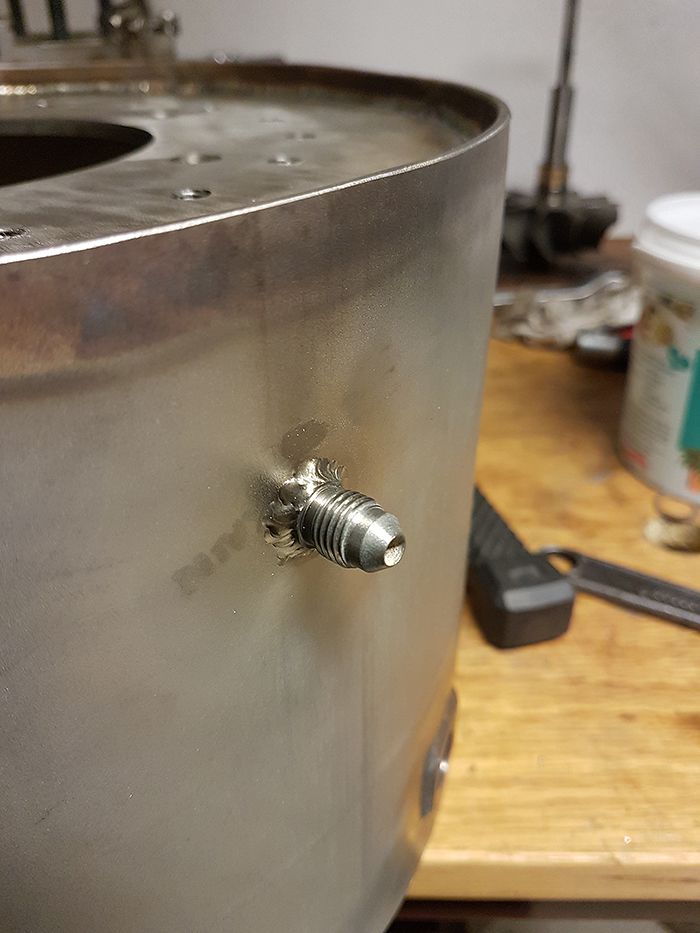 Here below I am in the process of welding a threaded fitting to the cover that will hold the propane preheater. I am trying out a Pyrex gas lens for the tig welder, nice to get that extra field of view of the part I am welding. 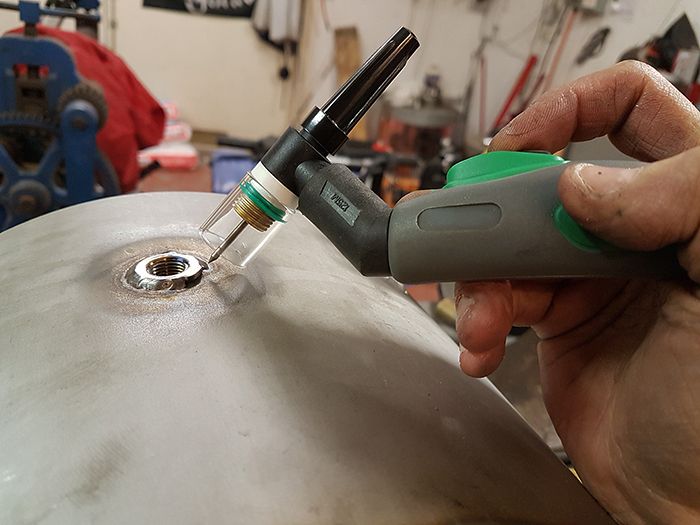 The idea in the long run is to use a small camping propane bottle strapped to the bike for preheating, but during the bench tests I will probably use the old and trusted 5kg propane tank. I have also bought a timer module since I need to preheat the glow plug for 10-15s before the gas valve is operated, if not the gas won´t light. 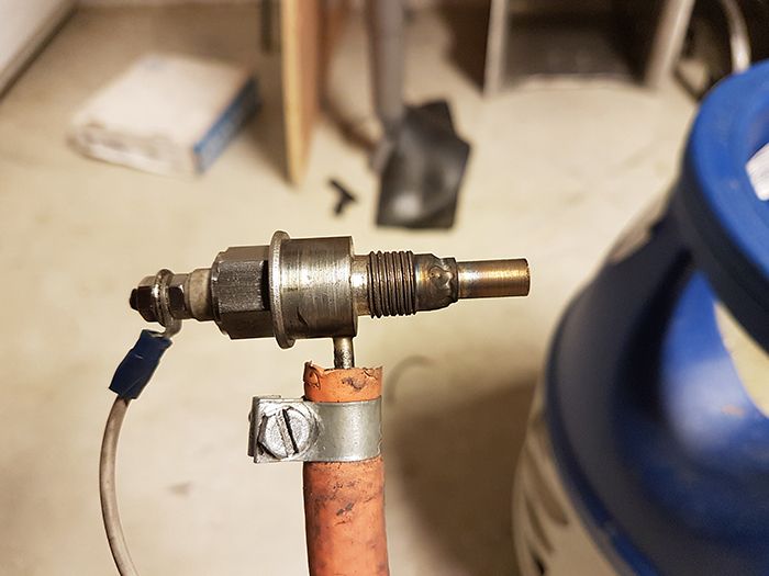 Plenty of graphite lube on the threads since stainless threads have a nasty habit of fusing together. 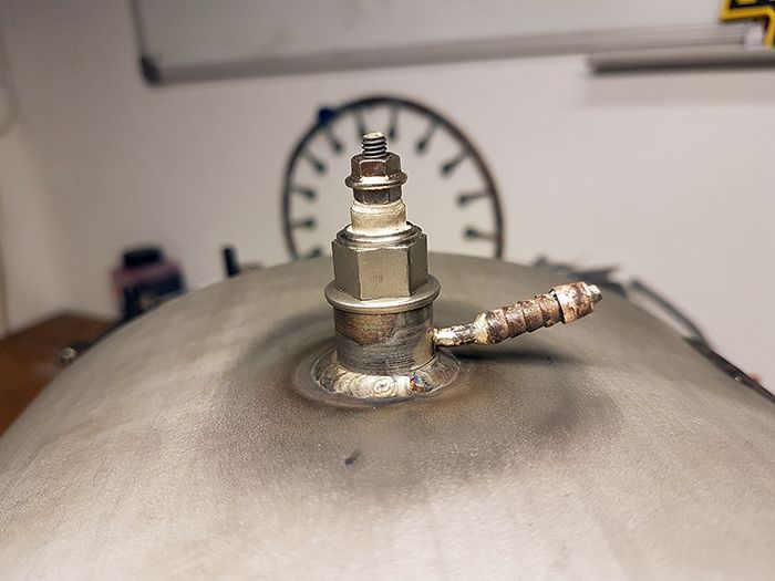 Here you can see the preheater sticking into the engine, I will mark and drill a hole in the combustor outer liner in which the preheater tip will protrude. 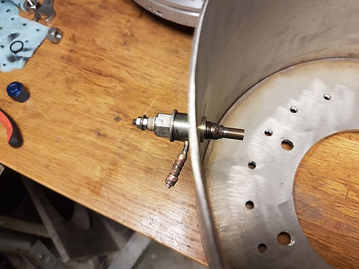 Cheers! /Anders |
|
|
|
Post by Johansson on Jan 27, 2017 17:12:50 GMT -5
I got a day off work since I´ve been on call for a week, so with my feancee at her job and kids at school I got lots of work around the house done. Some of it in the workshop. Here you can see that it is just a little bit of grinding needed for the preheater end to fit into one of the combustor holes. 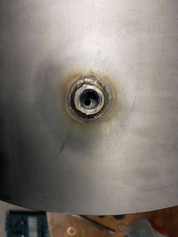 Aaaaaaaand....it fits! (engine is upside down for those who wonder why the oil drain is on top...) 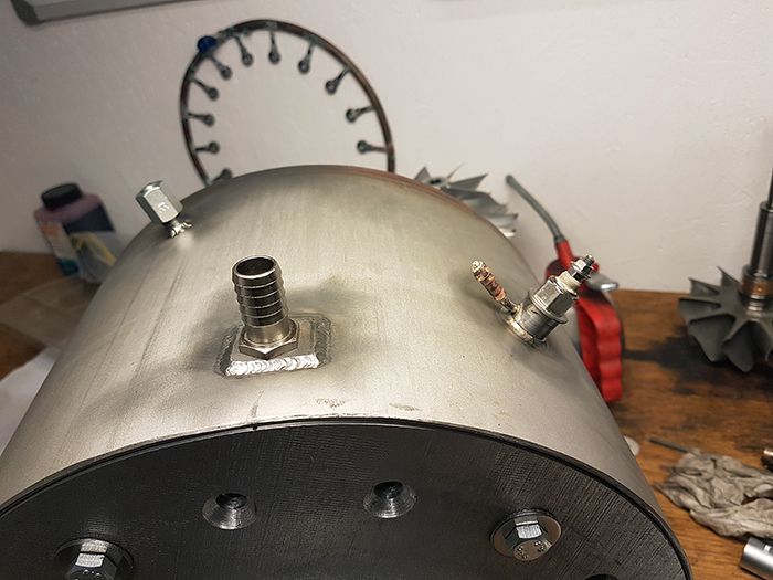 After that I spent an hour cleaning up the workshop and another wiping some chain lube from the bike and installing the rear fairings, but that is for another build thread. Good evening friends! |
|
|
|
Post by Johansson on Jan 28, 2017 16:59:36 GMT -5
After the kids were put to sleep I went to the workshop to get an hour of work done on the combustor, first job was to open up the clearance between the combustor lid and the oil return line. I welded the cut after the pic was taken. 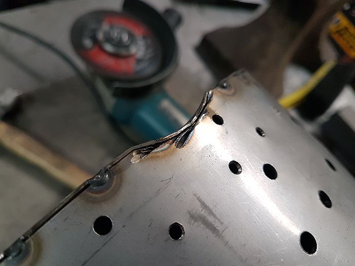 Then I angled some of the liner holes according to John´s JU-01 combustor drawing, the JU-02 combustor design is more or less a copy of JU-01´s since it has worked very good for me. 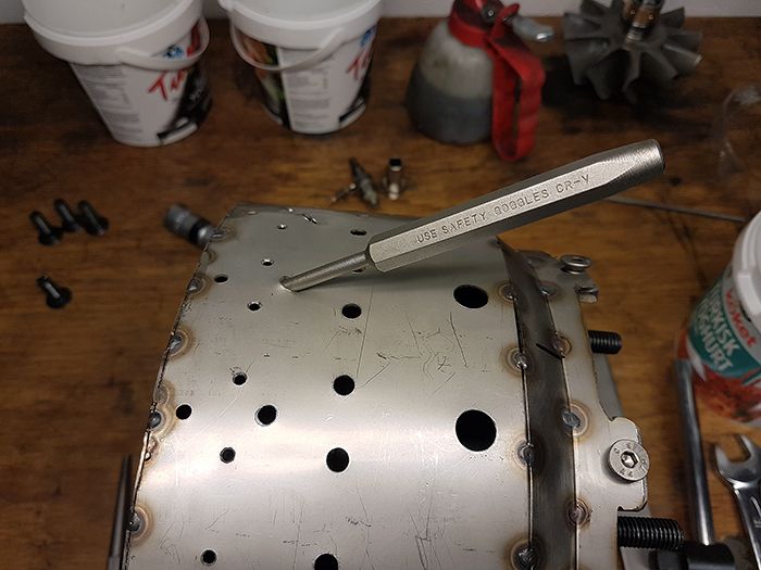 Before the evaporator tubes could be welded to the NGV I had to give them some D-ing to improve the internal turbulence and hopefully get better mixing of the kero and air. I had a jig that I made for the JU-01 build so it was a quick job. 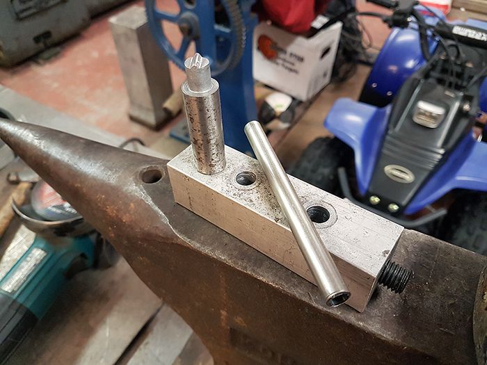 18 evaporators finished! 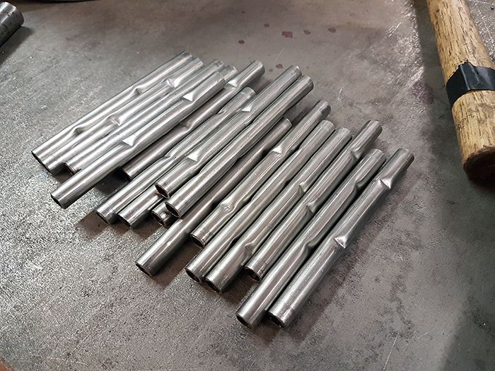 This is what they look like on the inside, 15 years of manual labor is starting to show on my hands by the way... 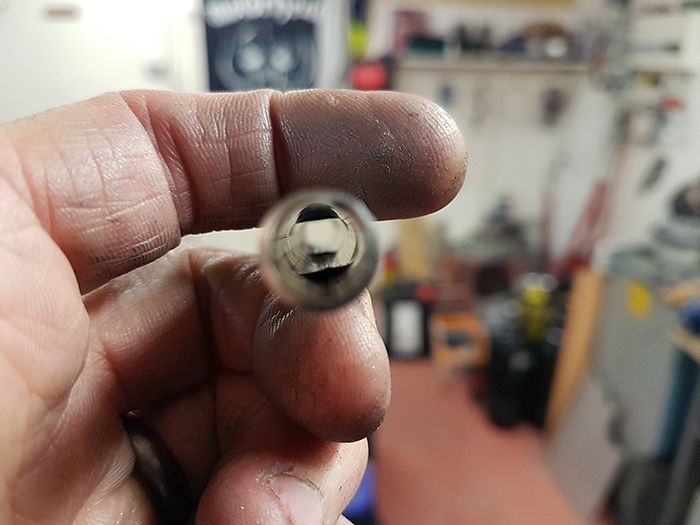 Then the evaporator tubes were welded to the NGV, I could have silver soldered them but I don´t have a gas torch powerful enough for the job and I kind of trust a tig weld more than solder. 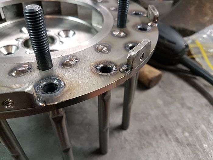 Another job on the list that can be crossed over, great!  Tomorrow we will do a test run on the lake with the jet kick sled, keep your fingers crossed! Cheers! /Anders |
|
|
|
Post by racket on Jan 28, 2017 17:20:16 GMT -5
Hi Anders
Nice welding job , if I could handle a TIG as well as you, I'd also be welding the evaps instead of silver soldering them .
Heh heh , I notice you have your D'ing on the inner and outer side of the evap , I have mine on the sides ............I'd guess it doesn't make any difference , the D'ing is the important thing to get some turbulence happening .
The engine is starting to look rather "finished" ............love the stainless work :-)
I like your lube line clearance solution , I tried just heating the end wall and beating a recess , but it didn't work , the 2mm thick stainless rollover at the corner was too strong, I think its the JFS turbine starter that has a large "recess" in its FT for clearance and still works OK .
All the best with the testing tomorrow, I hope you guys get to do a flawless run, its long overdue ..............video please .
Cheers
John
|
|


