|
|
Post by jetjeff on May 11, 2016 0:06:44 GMT -5
The turbine to shroud clearance was checked using strips of 3 x 5 index card (.008" thick). There still is some radial play with the card stock, I'd say the clearance is in the .010" to .012 range. Jeff  |
|
|
|
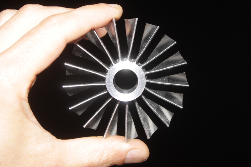
Post by jetjeff on May 15, 2016 6:14:13 GMT -5
Hi All, Making progress on the shaft. The 'bearing spigots', as Mr. Schreckling calls them were machined from aircraft quality 4130 chrome moly. Bearings are standard ball-races, grade 5. Also shown is a pic of how NOT to make a turbine wheel, blades way too thick 3/32" along side this build 3/64" thick. Jeff    |
|
|
|
Post by jetjeff on May 15, 2016 6:53:18 GMT -5
Another pic of the semi completed shaft.  |
|
|
|
Post by jetjeff on May 15, 2016 12:14:14 GMT -5
Here is my lathe setup for boring the rear bearing journal. I know, rather shitty, but your forced to improvise with limited equipment. I have a boring head for my Bridgeport, probably could have done it with that also. Kurt states the rear bearing must be of a sliding fit, but I'm assuming he didn't mean cold. Rear bearing has about .002" interference fit, front bearing has about .003" interference fit. Jeff   |
|
|
|
Post by jetjeff on May 18, 2016 4:19:44 GMT -5
Hi All, I need help with determining the number of hooked flame tubes for this engine. Page 91 in the Kamps book gives this formula for calculating it, but my numbers don't add up. f= the square root of 18,200 x d squared x h (I'm assuming d is compressor diameter and h is the exit height of the blades). My compressor is 90mm diameter and 9.5 exit blade height. So the mathematical equation is the square root of 18,200 x 8100 x 9.5 which is 1,400,490,000 =  Jeff |
|
greazy
Veteran Member

Joined: December 2015
Posts: 128
|
Post by greazy on May 18, 2016 5:02:10 GMT -5
square root of 1.400.490.000 is 37423
|
|
gtbph
Veteran Member
Joined: August 2013
Posts: 101 
|
Post by gtbph on May 18, 2016 18:41:38 GMT -5
Hi Jeff,
I guess the formula for the number of tubes is 18200*0.09*0.0095 = 15.56.
The other one "f = sqrt(3030*d2*h)" is the scaling factor for the holes.
Very nice and interesting build, please keep posting!
Cheers
Alain
|
|
|
|
Post by jetjeff on May 18, 2016 22:06:33 GMT -5
Hi Alain,
Thanks for the help with the math. Whew, 15 (or if you round up, 16) seems like a lot.
I'm almost wondering if the Kamps formula used the inducer diameter, instead of the exducer. Not sure, he wasn't specific.
I've watched the youtube video of the German gentleman who made the 2:1 scale Schreckling engine. It looks like he used 10 flame tubes from what I could tell.
Thanks, I will keep posting my progress. The shaft is almost complete, I machined the central tube down the needed length and just have to press the bearing spigots in and pin it with roll pins. Hopefully this weekend I can make significant progress on the combustion chamber.
Jeff
|
|
|
|
Post by racket on May 18, 2016 23:55:41 GMT -5
Hi Jeff
For evaporators I use total cross sectional flow area of all tubes equal to 10-12% of the compressor wheels inducer , and total heating surface ( wall OD area)of all evaporators as 6 times inducer area .
If you don't feel that 15 evaps look "right" , reduce the number and go up a size in diameter .
Cheers
John
|
|
|
|
Post by jetjeff on May 19, 2016 2:33:45 GMT -5
Hi John,
Thanks for the info.
Jeff
|
|
|
|
Post by jetjeff on May 21, 2016 22:45:38 GMT -5
Hi All, Here is the finished shaft. I checked the straightness using V blocks and a dial indicator (less than a 1/2 a thousandth). The bearing spigots were pinned to the tube with 1/8" roll pins not shown in the pictures. Jeff   |
|
|
|
Post by jetjeff on May 22, 2016 1:40:53 GMT -5
Here are the weights of the individual components for the old build vs the new build (in pounds);
Old-------------------------------New
1.10 Compressor diffuser -----.77
.30 turbine----------------------.30
.85 N.G.V.-----------------------.75
.30 turbocharger wheel---------.15 Schreckling wheel
.48 shaft tunnel-----------------.50
.41 shaft-------------------------.48
1.0 combustion chamber--------1.19
.77 compressor cover-----------.30
.94 outer case-------------------1.10
|
|
|
|
Post by jetjeff on May 23, 2016 4:16:08 GMT -5
Hi All, I didn't get as much done on the combustion chamber over the weekend as I hoped, but I was able to use an online 'cone calculator' to draw out the cone and add the lines for the hole placement for the inner liner. Material is 321 stainless .016" thick. Jeff  |
|
|
|
Post by jetjeff on May 23, 2016 4:17:57 GMT -5
Whoops wrong photo, here is the correct one.  |
|
Adam
Veteran Member
Joined: May 2016
Posts: 101
|
Post by Adam on May 27, 2016 1:00:47 GMT -5
Looking good Jeff! Thanks for the inspiration. Is the shaft hollow? Whats it made of?
|
|