alan
Member

Joined: August 2010
Posts: 36
|
Post by alan on Apr 3, 2017 0:02:49 GMT -5
|
|
alan
Member
Joined: August 2010
Posts: 36
|
Post by alan on Feb 26, 2017 23:30:07 GMT -5
I have 6 PCBs for a tachometer based on Sal Aiello's design that was modified and drawn by an electrical engineer. For more information see Laser Tachometer With Over Speed and Yahoo/DIY Gas Turbine group/Files/Designs and Ideas/Sals stuff/Tachometer Price list in USD (does not include shipping): Complete assembly(PCB, box, meter...) ---------- $75 Assembled PCB only---------------------------------$55 PCB only (no components) -------------------------$15 PCB plus components I have in stock---------------TBD *There is no profit made. The price covers parts and materials only. Location: United States. Estimated shipping time for completed boards is 2 - 3 weeks. Need time to order parts and assemble boards. PCB only will be shipped within 2 days. |
|
alan
Member
Joined: August 2010
Posts: 36
|
Post by alan on Jan 11, 2015 14:15:02 GMT -5
That is an interesting project you got going on there! What line of work do you do for a living?
|
|
alan
Member
Joined: August 2010
Posts: 36
|
Post by alan on Sept 19, 2014 6:50:19 GMT -5
Thank you Ian. Both those methods look doable. Ill post pictures when we try it.
Alan
|
|
alan
Member
Joined: August 2010
Posts: 36
|
Post by alan on Sept 17, 2014 22:39:47 GMT -5
Update
The stove pipe has been removed from the Allison and we are searching for exhaust stacks with a 90 degree bend. A few phone calls have been made to try and get some unairworthy exhaust stacks donated, but nothing looks promising.
If anyone knows of a company that might have exhaust stacks for an Allison 250 (T63 or C20B), we would like to know about them.
While we search for the exhaust stacks, the second major issue needs to be addressed, which is the drive shaft alignment.
We were told that the output shaft of the engine, intermedite shaft and input shaft of the dyno have to be almost perfectly aligned. There does not seem to be a good way to measure the alignment of the shafts. If anyone knows a good method to aligning a driveshaft, we would really appreciate it if you could explain it to us.
Thank you.
|
|
alan
Member
Joined: August 2010
Posts: 36
|
Post by alan on Sept 7, 2014 22:37:30 GMT -5
Smithy,
Thank you for that Mil spec. It's a relief to know I can contact someone who has experience with this engine. I was told that this engine should not need any maintenance done to it other than adding oil. I’ll have more questions for you after we solve the exhaust ducting and driveshaft setup problems and are close to running the engine.
Ian,
Unfortunately, the exhaust outlets of the engine point strait up. Actually if we had an exhaust fan in the ceiling then we could bring some ducting down from the fan and catch all the exhaust without creating any backpressure. I am going to look into that a little bit more.
|
|
alan
Member
Joined: August 2010
Posts: 36
|
Post by alan on Sept 5, 2014 22:37:30 GMT -5
Now there are two main issues that need addressed before we can even think about running the engine.
One issue is that we have to vent all the exhaust outside of the test cell. One day I came in to do some more work and found stove pipe bent around the exhaust oultets.
I need replace this cheap exhaust ducting with something else, but im not sure what. My request to purchase unairworthy exhaust stacks got denied. So I am open to any suggestions.
|
|
alan
Member
Joined: August 2010
Posts: 36
|
Post by alan on Sept 5, 2014 21:50:30 GMT -5
Well progress is coming along slowly but surly. The main control box is turning out okay after we drilled the holes switches and LEDs upsidown  . to fix it we just cut the whole section out and make a new front panel that we will rivet on later. Also, if anyone has access to a manual for this Allison (t63) 250, I would like to know the right type of oil we need to use. If someone could get this information to me or even better, show me where I can access a manual it would be much appreciated   |
|
alan
Member
Joined: August 2010
Posts: 36
|
Post by alan on Aug 7, 2014 5:28:18 GMT -5
nersut,
check your messeges, I sent you one.
|
|
alan
Member
Joined: August 2010
Posts: 36
|
Post by alan on Aug 2, 2014 23:53:37 GMT -5
Here is the schematic. 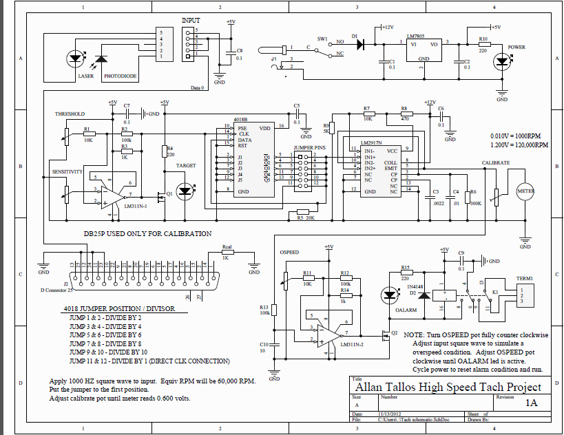 This was designed to work with black and white painted spinner. It can also use the flats on the comp nut to calculate rpm, you just need to change the jumper position. |
|
alan
Member
Joined: August 2010
Posts: 36
|
Post by alan on Jul 31, 2014 18:20:58 GMT -5
A while ago my friend, who is an electrical engineer, took Sal's tachometer design, which did work, and modified in a way to make it a little better and he added an over-speed protection circuit which incorporated a latching relay. We got about 10 boards printed out and I have all the components, but he ended up moving away and we lost touch. My friend, Roger, said, in theory it could sense over 120,000 rpm. It might be possible to sense the high rpm range you are looking for John. I still have everything, and the cost per unit ended up being around $40 with shipping within the US. I am afraid I still do not have the time to dedicate to completing this project. So if someone would like put one of these boards together and do some testing, then I would be willing to ship a board and the components out. I know it's not "off the shelf", but it is an easily affordable option. 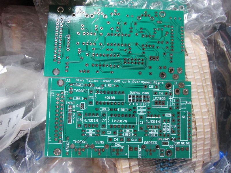 |
|
alan
Member
Joined: August 2010
Posts: 36
|
Post by alan on Jun 12, 2014 20:42:18 GMT -5
First on the list of things to do is make the test stand safe for students and to protect if from students.
The power receptical use to be mounted in the open under where the oil hoses disconnect. the junction box will now enclose the power receptical and I will also mount away from the oil lines.
The oil pump for the dyno use to be mounted to the wall of the test cell, so we re-mounted it to the dyno's test stand.
The fuel boost pump was also mounted in an inconvienant location and if you look at the wire coming of it, it has a cheap automotive butt spice. There are a lot of little discrepancies like this that we have fix.
|
|
alan
Member
Joined: August 2010
Posts: 36
|
Post by alan on Jun 10, 2014 21:09:26 GMT -5
Hello Everyone!
For my senior project at college*, two classmates and I are completing the setup of the Allison 250 test cell. This test cell incorporates a dynamometer and a data acquisition unit that feeds information to a computer in the control room where the info. is displayed on a computer monitor.
The main goal is to setup the test stand so swapping the two Allison engines we have will be fast and easy.
This is my first time working with this engine and a dyno so it will be a great learning experience!
|
|
alan
Member
Joined: August 2010
Posts: 36
|
Post by alan on May 23, 2013 23:41:52 GMT -5
Ha nice job with the igniter. Thats the circuit Johanson posted for me. I got it to work only to find out the coil was bad, not sure why though, I only pulled it out of a scrap pile lol.
|
|
alan
Member
Joined: August 2010
Posts: 36
|
Post by alan on Nov 10, 2012 12:29:08 GMT -5
|
|


 . to fix it we just cut the whole section out and make a new front panel that we will rivet on later.


