userscott
Junior Member

Joined: March 2019
Posts: 96
|
Post by userscott on Jan 9, 2020 8:16:01 GMT -5
Great thread Scott and has been helpful in ideas for my first build about to start. I will look forward to seeing this run, Im UK also but in the warm sunny south. Thank you, glad it's been of some help. What's your project? I've been doing a bit more wiring. I've got rid of the automotive flasher relay as it wasn't easy to package in - switched over to a 12V DC timer which I can then set to work how I want - either alternating the coil on and off repeatedly or holding it on for X seconds after I press the button. It's untested yet, but it's coupled up to a suitable relay so I do expect it to work but I'm ready to be disappointed...  |
|
Colin Heath
Junior Member
Joined: January 2020
Posts: 77
|
Post by Colin Heath on Jan 9, 2020 13:37:55 GMT -5
Great thread Scott and has been helpful in ideas for my first build about to start. I will look forward to seeing this run, Im UK also but in the warm sunny south. Thank you, glad it's been of some help. What's your project? I've been doing a bit more wiring. I've got rid of the automotive flasher relay as it wasn't easy to package in - switched over to a 12V DC timer which I can then set to work how I want - either alternating the coil on and off repeatedly or holding it on for X seconds after I press the button. It's untested yet, but it's coupled up to a suitable relay so I do expect it to work but I'm ready to be disappointed... My project should be called “In trouble already” but will eventually be a turbo shaft driven ride on lawn mower. Got a largish car turbo but stripped it and all the bearings fell out 😂 Garrett can’t identify it by numbers that are stamped on it so be fun getting parts. Anyway, I like the idea of timer for coil, what is maximum frequency you can turn on and off for spark production? We used to use a D.C. relay hooked up to AC for a lashed up coil driver for high voltage fun. Dimmer switch is another but would require AC. I did build a double 555 timer board years ago that you could separately change on time and interval to change power. That gave a nice juicy spark. |
|
userscott
Junior Member
Joined: March 2019
Posts: 96
|
Post by userscott on Jan 27, 2020 19:31:12 GMT -5
- I guess I need to get my spark plug to the side, further down the can now, and I assume line it up as best as possible with some of the holes in the flame tube? - I can still squeeze my propane injector somewhere down the side of the evap setup for use when starting? Project has been on hold for a few weeks for travel in America. On the flight home now and getting on with the last bits of design for the FT. The above two questions have came back around and I'd be keen to get the collective view on them - in short even after reading most threads on here my questions remain: - I've now got the 180 degree McMaster nozzle on its way (https://www.mcmaster.com/3178k51) - would it be more optimal to have the flow of the kerosene hitting the FT in line with the primary holes or between primary and secondary? This is the pump I'm using walbrofuelpumps.com/walbro-gsl392-inline-fuel-255lph-pump.html- Have people reliably ran with the spark plug in the removable cap of the CC or is it better in the side of the tube (and if so top or bottom?) - Do people have a suggested oil pressure that I should configure my pump to achieve? I have seen a lot of variation on threads.. - I still intend to start on Propane - I'm envisioning a tube that runs through the CC cap, and past the primaries and secondaries, with X amount of small holes drilled in it. Have I missed anything obvious and is there a collectively agreed optimal length? Cheers as always.... |
|
userscott
Junior Member
Joined: March 2019
Posts: 96
|
Post by userscott on Jan 28, 2020 13:49:16 GMT -5
Here is my proposal for the Flametube and the supporting info from Jetspecs..   |
|
|
|
Post by racket on Jan 28, 2020 15:36:48 GMT -5
Hi
If you intend using kero I'd be inclined to change your hole sizes , Jetspecs assumes/prefers propane injection so a lot of small Primary holes will work OK as the propane has excellent combustion characteristics unlike kero which requires more "sophistication" to provide recirculation within the Primary Zone , your 4 mm holes will have minimal penetration into the flametube, you need some 8mm holes .
The number of secondary holes could also be reduced to 12 or less
Cheers
John
|
|
userscott
Junior Member
Joined: March 2019
Posts: 96
|
Post by userscott on Feb 7, 2020 8:47:09 GMT -5
Hi If you intend using kero I'd be inclined to change your hole sizes , Jetspecs assumes/prefers propane injection so a lot of small Primary holes will work OK as the propane has excellent combustion characteristics unlike kero which requires more "sophistication" to provide recirculation within the Primary Zone , your 4 mm holes will have minimal penetration into the flametube, you need some 8mm holes . The number of secondary holes could also be reduced to 12 or less Cheers John Thanks as ever, John. I'll incorporate these changes and then will upload my final version.  Bit of an update and some challenges...  So the oil pump has caused a tale of woes. I'm using a Volvo S80 (ZF) power steering pump mated to a Parvalux DC Motor (A50-3096B). This is a 12V, 3600 RPM, 110 Watt DC motor (ebay 333164560356). I originally had this powered by a 4QD SST-031 controller as I'd calculated the current to be within the parameters of this controller. Quickly I realised something was amiss with my calculations and let the magic smoke out after a few minutes of running. I used 2.5 mm2 cable, 10W40 oil and managed around 30 PSI before blowing the fuse. Obviously a few school boy errors to get to this point..! I have since changed the motor controller to a 4QD Porter 10 (100 Amp) controller - in the picture above, you can see the new speed controller wedged in under the coil. This allows me to get around 35 PSI before things get warm. I'm obviously in a sticky wicket as I've gone too far in packaging this system into the chassis without testing it and realising it didn't work as intended!  I am now in process of changing the cabling up to 6 mm2, will reduce the viscosity of the oil to something as thin as I dare, and have read some suggestions of drilling the relief ports in the pump to increase the flow and reduce the pressure. I'll whip it apart and take a look at this over the coming nights. A lot of online sources seem to suggest pre-heating the oil - with either a DC self adhesive sump warming pad or alternative methods... I don't really want to do this! Otherwise I need to scrap my current pumping setup and replace it with a pre-manufactured (and very expensive!) MoCal or similar unit.... Potentially a Marco UP12 would make all my problems go away........... Is this worth doing? I've seen these on a lot of other build threads!  I've weighed her in her wet weight.. I think we are now looking at a final build weight with oil and fuel of 150 KG. It's obviously quite a bit, but there is negligible friction on the rails. I know we've talked about this earlier in the thread but I'm really not seeing the weight as an issue at this stage. I may eat my words in future posts............! |
|
|
|
Post by racket on Feb 7, 2020 15:59:02 GMT -5
Hi
Power steering pumps often need internal modifications to get them working "correctly" for our use , I can't remember exactly whats required , but check valving , otherwise current draw is too great .
The build is coming together nicely :-)
Cheers
John
|
|
userscott
Junior Member
Joined: March 2019
Posts: 96
|
Post by userscott on Feb 10, 2020 12:45:56 GMT -5
Two steps forward, one step back! I dismantled the pump and removed the flow restrictor - seen here, the little brass plug.  It came out and left a nice neat hole, but I drilled it up one size "as a guess" against all recommendations when doing this sort of thing, as I was confident it would be something like right, plus the pumps are cheap and mine needs replacing ideally as this shaft was damaged slightly - nothing to lose.  Upon rebuilding the pump, all my electrical concerns have gone away. She spins smoothly and freely. However, I'm only getting 40 PSI. This is either because I'm not spinning her fast enough, or because I've gone too large on the drill. My gut feeling is I'm not spinning her fast enough, so I'm wondering if 40 PSI will be satisfactory for our needs. The major issue I had was foaming of the oil - I know there's been a million threads on here of how to resolve it - so I will undertake some reading and try and get to the bottom of what's causing it in my application. My return feed vents into the tank "underwater" which I thought would help.. |
|
|
|
Post by turboron on Feb 10, 2020 15:37:19 GMT -5
Colin, the discharge of the oil drain should be about the oil level through an aeration plate to allow the air/exhaust gas seal leakage into the sump to separate from the oil if possible.
Thanks, Ron
|
|
|
|
Post by racket on Feb 10, 2020 15:55:26 GMT -5
May I suggest you disconnect the lube line from the turbo and do a flow test of the system to determine exactly how much flow your pump is capable of, then you can work back and calculate the power required, your 110W might be a bit shy of whats required
Cheer
John
|
|
userscott
Junior Member
Joined: March 2019
Posts: 96
|
Post by userscott on Mar 3, 2020 9:16:13 GMT -5
May I suggest you disconnect the lube line from the turbo and do a flow test of the system to determine exactly how much flow your pump is capable of, then you can work back and calculate the power required, your 110W might be a bit shy of whats required Cheer John Hi John, I made a few attempts at checking it and quite comfortably established that It delivers 8.5 LPM at 45 PSI. I have identified that the relief valve in my power steering pump is just not suitable for this higher level of LPM (I have significantly drilled the pump pressure valve out, one could say too much!) Regardless, I intend to fit an external PRV such as this. I can easily set this to the exact requirements of the turbo and then use the PWM to reduce my flow.. It's not cheap but if I can PRV to 40 lbs I can then up the PWM when the oil gets thin etc.  I realised I made some significant non-conformances with the installation manual for my turbo. I have now removed my entire return system and I'm ready to fit something far more in check with what the manufacturer suggests. My only question is the return to the chassis. The manual states there must be a 50 mm air gap between the top of the oil and the "Return", and I've incorporated into my design two mesh plates and one low density porous foam. Does this seem sensible?   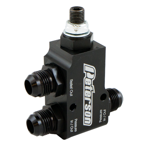 |
|
|
|
Post by turboron on Mar 3, 2020 15:36:15 GMT -5
userscott, not sure what you are showing. The return oil has entrained gas leakage from the compressor and turbine seals. If you have a vented to atmospheric tank you must give the oil and gas mixture a chance to separate. Best practice is to have a horizontal perforated plate the full size of the tank. The oil exits the drain line above the perforated plate and impinges on the plate separating the oil and gas mixture. The oil level is below the perforated plate.
If you don't vent the tank then you must use a centrifugal separator to remove the gas.
Thanks, Ron
|
|
|
|
Post by racket on Mar 3, 2020 16:06:17 GMT -5
Yeh, as Ron said , you need to have an "unrestricted" downhill flow to the tank , your mesh will restrict flow , the tube from the turbo needs to be the same ID as the turbo port and then have it enter the tank well above the oil level to allow for some "expansion" of the contents due to air/oil entrainment , I fitted a perforated plate ibb.co/jrwyXC7 into my tank that the oil will discharge onto to aid in removing air . |
|
userscott
Junior Member
Joined: March 2019
Posts: 96
|
Post by userscott on Mar 4, 2020 8:05:21 GMT -5
Ron, John, thanks very much for your responses. This makes sense now. To explain, my oil tank is the RHS chassis rail which measures 1000 x 100 x 50 mm. The drawing is a "cut out" of this chassis - a 100 mm x 100 mm x 50 mm section showing my new proposed return. As the tank is fully enclosed by nature of its design I'm a bit stuck. Now it is vented thankfully, but very difficult to cut open. As a compromise, I have drawn up the following which I think I can fit after some careful angle grinding....  |
|
|
|
Post by racket on Mar 4, 2020 15:26:58 GMT -5
Thats a bit better :-)
|
|


