|
|
Post by racket on Dec 4, 2012 15:21:39 GMT -5
Hi Sven
We have rather high airflow speeds between compressor housing and combustor so any sharp 90 degree changes of direction are to be avoided at all cost , this rules out the 3 legged one and the opposed twin tube delivery , and unfortunately I can't recommend the remaining one as it dumps all the air against the primary zone which can cause combustion problems .
Try using a 180 degree circular bend and dump the air in at the outlet end of the combustor .
Cheers
John
|
|
sven
Veteran Member
  
Joined: February 2012
Posts: 102
|
Post by sven on Dec 4, 2012 15:51:45 GMT -5
Hi
thanks guys for reply.
John you mean that I should use short 180 degree bend and dump air next to the combustor outlet(next to the turbine inlet vanes) Tertiary zone?
Cheers
|
|
|
|
Post by stoffe64 on Dec 4, 2012 17:11:28 GMT -5
well, John i know that you want the entrance by the turbine side of the combustor, but out of the 3 types that single pipe one was the best to choose.
|
|
|
|
Post by racket on Dec 4, 2012 18:11:02 GMT -5
Hi Stephan
Yeh , the single pipe was the least problematic , but it still wasn't a good setup , I don't know why guys insist on mounting the pipe at that end when we are trying to produce good combustion and there'll be a 100 metres/sec blast against the flametube holes .
Cheers
John
|
|
|
|
Post by racket on Dec 4, 2012 18:15:27 GMT -5
Hi Sven
Yes , have the air entering at the Tertiary zone near your NGV , theres a small pressure drop across the flametube wall , this means the air will flow to all parts of the combustor to enter the flametube wall holes , and as we only want ~30% at the primary end its easily achieved .
What sort of flametube are you going to make ??
Cheers
John
|
|
Feathers
Veteran Member
  
Joined: August 2010
Posts: 169
|
Post by Feathers on Dec 4, 2012 21:46:27 GMT -5
I know why most people (me included) go for that setup.....
Maybe because they see it with the Allison 250,
But primarily because RCDon did it.
He uses alot of intuition to build cool projects that work very well, and his craftsmanship is incredible, but he isn't always perfectly advised.
I fell into that trap in several regards, adding a (very small) "bypass zone", and plumbing the combustor inlet up towards the primary section of a very relatively skinny combustor.
I haven't run into any issues yet, but we'll see what happens when I bolt on a nozzle and properly load the engine...
|
|
Feathers
Veteran Member
  
Joined: August 2010
Posts: 169
|
Post by Feathers on Dec 4, 2012 21:48:40 GMT -5
Fantastic project by the way!
You've done pretty crazy work with the tools you have.
|
|
|
|
Post by racket on Dec 5, 2012 0:41:58 GMT -5
Hi Feathers
The Allison 250 does indeed feed the air to the primary end of the flametube but there are huge diffusing "bulges" on each side of the combustor can that slow the air down considerably and distribute air to all areas of the flametube , this distribution is aided by baffles withing those "bulges" with metering holes in the baffles , the 250 can is a complex bit of equipment compared to our DIY combustors , the air entry to those "bulges" is roughly opposite the secondary air holes , so that the "bulges" cover both the primary and tertiary zones as well , ............theres no high speed air impinging on only one side of the flametube in the primary zone .
Yep, RC Don does beautiful construction and I'd recommend his Site to anyone for inspiration in that direction , but not for the "theory" , its only repeating what someone else has repeated from a suspect source .
Cheers
John
|
|
sven
Veteran Member
  
Joined: February 2012
Posts: 102
|
Post by sven on Dec 5, 2012 3:03:59 GMT -5
Hi
Thanks for replys.
John , not sure about flametube jet. I was thinking about make replica,
What you and Anders made for your engines. I also like style what you John
made for your afterburner kart. This flametube style might be the one.
Any suggestions maybe?
thanks a lot again guys.
cheers.
Sven
|
|
sven
Veteran Member
  
Joined: February 2012
Posts: 102
|
Post by sven on Dec 13, 2012 7:41:05 GMT -5
Hi
Heating trials what I made for turbine housing(for all made parts) results I dont like, I choosed too thin steel for backplate what start warping when heated, that means turbine wheel starts rubbing:S I dont like make things that lasts 1 minute. ;D
Cause I put too much time and efford to this project already, and dont want to to it again, Im gonna use already made parts and convert my (radial,axial type?) combustor chamber into thumb style combustor, and gonna use original turbine scroll to deal with heat. I made already nice drawings how convert it into nice compact thumb combustor style engine.
Im gonna make some changes for this thread, but right now Im ill at home, gonna take some time for myself.
I promise its gonna be good engine,but slightly changed:)
New pics coming soon, also pile of parts arrived to me:)
Cheers Sven
|
|
sven
Veteran Member
  
Joined: February 2012
Posts: 102
|
Post by sven on Dec 14, 2012 8:02:54 GMT -5
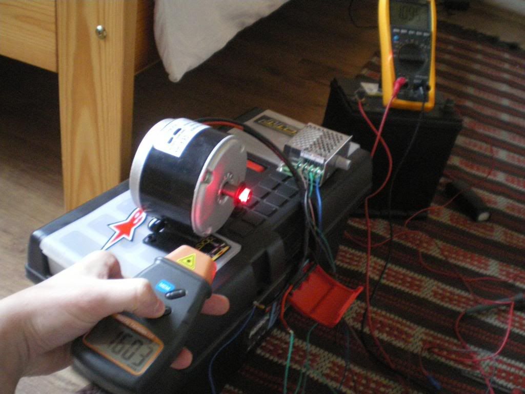
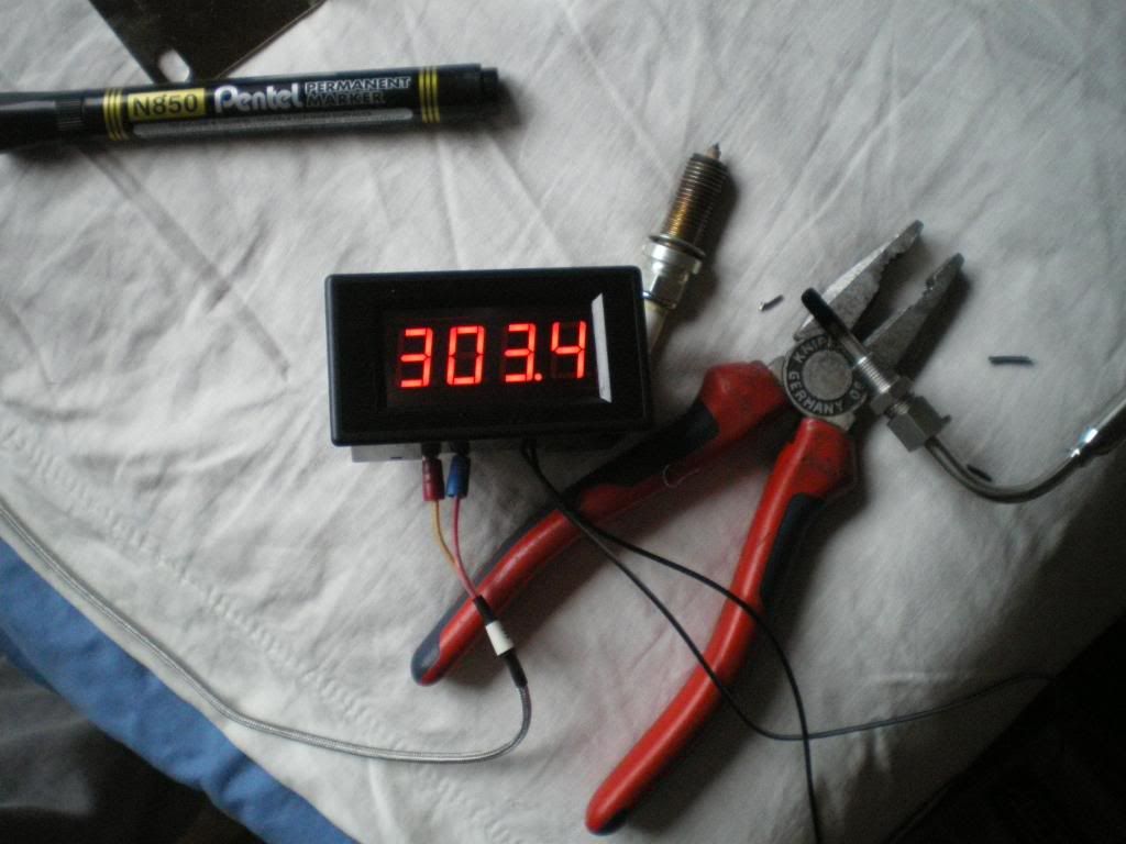
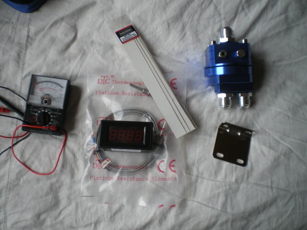
Hi Today I tested oil pump motor, pwm regulating system. Works nicely, regulating speed 50-1600 rmp @ 12V (drawing 1,1A)  Tested K type EGT sensor and display up to 300 Celsius (with my lighter)  Very nice working order, reaction time is quick. Max temp for probe 1200 Celsius.  Here you see more stuff arrived to me  Cheers Sven |
|
|
|
Post by Johansson on Dec 14, 2012 15:27:59 GMT -5
Very nice parts!
|
|
sven
Veteran Member
  
Joined: February 2012
Posts: 102
|
Post by sven on Dec 15, 2012 5:33:02 GMT -5
Thanks Anders,
Today ordered AN fittings,weldbungs,braided hoses, adapters for oil süstem. 2x 120mm slim cooling fans aso. Not good for credit card,but when ill @ home ;D there is not much to do.
Sven
|
|
sven
Veteran Member
  
Joined: February 2012
Posts: 102
|
Post by sven on Dec 19, 2012 11:45:27 GMT -5
Like I said before, there will be some changes making this engine. So I made a frame for my engine, turbine intake flange+90 degree bend, Old fire extinguisher for combustor. Combustor is bit small, but hope it gonna work. My comp inducer is 70mm, comustor ID is 147mm lenght 360mm. Flametube I was thinking to make measures: ID 115-120mm and 360mm in lenght . 90 degree bend OD is 90mm its gonna add some lenght.(hope its good) jet specs suggesting flametube 140 mm by 420 lenghtExperts I need some feedback , is it good enought or i need definitely change my combustor. Some pics todays build     |
|
|
|
Post by stoffe64 on Jan 24, 2013 4:27:27 GMT -5
it should work,designed correctly with the great attention to details,but the simplest is ofcourse to follow jetspecs(myself dont follow it fully for my build,but almost) i know one guy who makes the combustors very small but then again he has been constructing real aircraft engines for over 40 years...attention to details simply and trial and error!
cheers/stephan
|
|