dond
New Member

Joined: February 2014
Posts: 8 
|
Post by dond on Feb 14, 2014 3:35:41 GMT -5
Hey guys, I just joined this board. I recently aquired a Fairchild J44 turbine that I'd like to get running. I've found a small bit of info on the net, and I was able to get a old instruction manual, but I'd still like to find some more detailed info on this. Mine is a a Rev 12, the only thing I've found any information on is a Rev 3. I'll post some photos in a day or two as well. Hopefully someone here has some experience with one of these and can help walk me through any difficulties. No rush- I realize this is going to take a while and it's a long term project, so I'm patient! Any thoughts or advice would be very much appreciated! Thanks in advance! -Don
|
|
cursorkeys
Veteran Member
Proper engines use the Brayton cycle
Joined: July 2012
Posts: 108
|
Post by cursorkeys on Feb 14, 2014 5:38:06 GMT -5
That's a nice early engine. It is vitally important that you try and copy E.J Potter's example with the correct use of them though   I'm not sure of an information source offhand. The manual you found was the Essco Aircraft one? Generally engines stay pretty similar as they get revised, with changes to improve power/reliability/assembility. The R3 information is probably still broadly applicable. Edit: Flight Global have a little bit on it. The R-12 was an expendable variant for missiles. There may not be any manuals available for this specific variant due to that, but if there is someone here will know of it! |
|
|
|
Post by racket on Feb 14, 2014 17:38:19 GMT -5
Hi Don
Welcome to the Forum :-)
Now thats an different engine , mixed flow , centrif to axial in the one comp wheel , my data gives a 2.7 : 1 Pressure Ratio with 25 lbs/sec mass flow and 1,000 lbs of thrust.
Pretty basic construction by the looks of things .
Looking forward to seeing some pics
Cheers
John
|
|
|
|
Post by finiteparts on Feb 14, 2014 22:26:06 GMT -5
Hey Don, I have two J-44s. One is a non-certified engine and the other is the certified for manned flight variant...I'll have to go out and check the numbers. But the manual for the -R-3 and the -R-24 are pretty similar. Those are the only two manuals that I have been able to get my hands on. There were changes in the fuel system, hot section materials, bearings, etc between variants, but the operation is pretty much the same. As for using the engine in a similar fashion as E.J. Potter, I think you should first remember that this engine was made in the 1940's when they didn't x-ray rotors for foreign inclusions or voids....if your's is like mine, you have absolutely no idea of the number of cycles that have been put on the engine or if it has ever been over-speeded...and many of these were trade school engines due to their simplicity, so who knows who worked on them...so to make a short story long, I would be no where near the plane of rotation of one of these in operation and my engines will likely never go to full power either...but hey, maybe I am jaded because I have seen the aftermath of failures on large industrial turbines and current aircraft engines that are inspected and maintained way better than these ever were. I think you messaged me on Youtube...  Send me a PM if you want to chat about these. ~ Chris |
|
|
|
Post by finiteparts on Feb 14, 2014 22:28:45 GMT -5
Here are some images of my J-44's inner workings: Here is the mixed compressor wheel from the side...note that the inducer is one piece and the impeller is a separate piece. Casting considerations forced this design on many of the early centrifugal compressors...  Here is the rotor assembly of the non-certified variant...  This is the easiest way to tell if your's is a certified or non-certified variant...the manned flight rated engines have a fir-tree disc/blade design....  While the non-certified variants have a single cast turbine wheel...I would definitely not be anywhere near one of these while running it...if you know anything about castings, I am sure that you would agree.  If you engine is a non-certified engine inspect the turbine wheel and nozzle for cracks...mine has a ton of cracks in the nozzle guide vanes and a ton of sulfidation (or similar corrosion) on the wheel...   The rated RPMs are 15,780...that is a huge amount of energy!!!  Here is the diffuser and combustion sections. The diffuser uses three row of vanes to recover static pressure from the swirl energy of the compressor outlet flow. Early casting variations in the diffuser would commonly cause the compressor to surge...  |
|
dond
New Member
Joined: February 2014
Posts: 8
|
Post by dond on Feb 16, 2014 1:43:38 GMT -5
Thanks to all you guys for your replies! And yes, finiteparts, I did message you via youtube! Thanks for posting the photos and info as well. I'm hoping that this one if flight-rated, and no, I don't want to be anywhere near the rotational plane while it's running, flight-rated or not. I'd envisioned mounting it in the back of my Ford Ranger, NOT for drag racing or speed contests, etc. but just for the novelty of it. I don't know, given the projected lifespan of these engines and the condition of this one in particular, if that'll be desirable, but we'll see. If nothing else, it'll probably be a good turbine-starter project for me. Below are some photos I took when I got it home today. I'll probably be getting into the nuts and bolts part in a day or two, I'll post what I find on here. Thanks again to all! 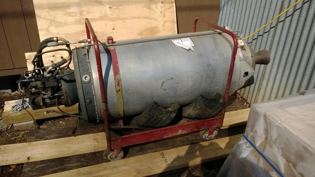 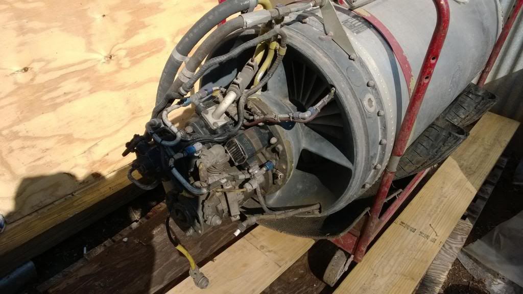 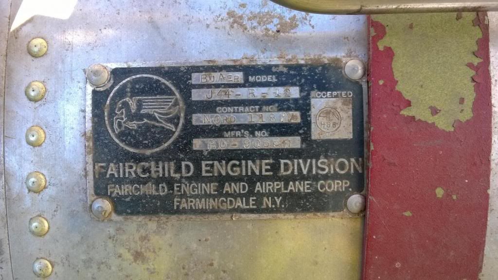 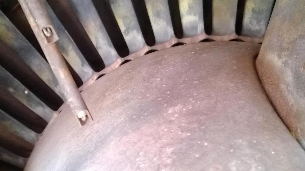 |
|
|
|
Post by turbochris on Feb 18, 2014 10:19:46 GMT -5
Farmingdale NY, my home town. I lived about a mile or so from fairchild. Don't run it w a cast wheel.
|
|
dond
New Member
Joined: February 2014
Posts: 8
|
Post by dond on Feb 24, 2014 1:17:28 GMT -5
|
|
|
|
Post by turbochris on Feb 24, 2014 9:05:48 GMT -5
you can run it in a secured area. running it in a crowded area for show is out of the question. Run it, learn, get the video, put it on display or blow it up! 45 degree rule! making this a reliable runner would be too dangerous/expensive IMO
|
|
dond
New Member
Joined: February 2014
Posts: 8
|
Post by dond on Feb 24, 2014 10:50:54 GMT -5
you can run it in a secured area. running it in a crowded area for show is out of the question. Run it, learn, get the video, put it on display or blow it up! 45 degree rule! making this a reliable runner would be too dangerous/expensive IMO Thanks for the advice Chris. And I agree wholeheartedly that runnning it in a crowd for show is out of the question. I don't mind putting myself at a *calculated* risk at times, but I wouldn't want to put someone else in that position. I assume the "45 degree rule" means I should remain >45deg out of the rotational plane if I do run it? I'd also considered making some kind of safety guard in case it does do a "Catastrosphic Rapid Rotational Disassembly"  ? But I wonder if that might simply worsen the risk by deflecting rather than absorbing the high-energy parts. Your thoughts? |
|
dond
New Member
Joined: February 2014
Posts: 8
|
Post by dond on Feb 24, 2014 23:44:57 GMT -5
The outer plate for the gearbox came off like I'd figured it would. The only bolts I could get were a little short so I cut some short steel dowel pins to insert in front of them and it came right off. Photos below. The gears, bearings, and seals appeared to be in excellent condition, with very litte if any use, although only 2 of the bearings rotated freely, presumably from being dry for so long. I'll probably replace all the bearings and seals, just to be on the safe side. I wonder if this gearbox ever had any oil in it? It looks like it might be dry from a fresh build/rebuild, but given the presumed age it's hard to tell. Photos below, and, as always, any feedback/advice would be appreciated. Now, *assuming* all else goes well, what will it take to actually run this thing? From a bit of research and taking it apart, I think I'm getting a better understanding of what's necessary. Here're my thoughts; Required Items
- Electrical supply for ignition coil, temp and tachometer monitoring
- Fuel supply
- Oil supply
- Compressed air supply for starting
1. It has a generator that's rated for 3 phase AC, 110V 400 cycle<Hz>. I'm thinking that I may be able to do away with this since I can probably build a more reliable power supply that's not driven by or an integral part of the engine itself. 2. Fuel pump/supply- again, I'd like to make my own. Probably using a high pressure fuel pump and 1 or more injectors for metering. 3. Oil supply- I'm thinking of a separate high pressure oil pump capable of supplying cooling oil through the and with the capacity for the oil lost cooling the rear bearing. From what I've read- the rear bearing uses an oil-mist and this oil is lost. Not sure about the front- I'll have to read some more. 4. Compressed air for starting- I'll use a small high pressure air cylinder, probably an old oxygen cylinder, and pressurize it with a high pressure pump to 2000-2800psi max (with AIR not O2!  for starting. My plan is to run all this with a PLC from a laptop. I'll tie the tach in with the fuel feed, adding safe RPM cut-out limits. Also tie in oil and fuel pressure and EGT readings with shut downs in case anything's out of acceptable ranges. I also understand that I'll need a positive fuel shut-off that cuts the fuel feed quickly, even in an electrical power failure state. How am I doing so far guys? EDIT- don't know why I'm having trouble attaching photos. I'll figure it out later! |
|
|
|
Post by finiteparts on Feb 25, 2014 23:19:22 GMT -5
Hey dond,
Your turbine, aft-cone, etc looks quite a bit different than my non-cert engine...my turbine bolts on as you can see in the pics. I just went out and checked, mine is a J44-R-24 (non-cert engine)...I am guessing a newer variant. Yours look just like the ones on the Bell VTOL aircraft...
Both of mine have self-aligning bearings at either end...they are like a radial ball bearing with the outer ring mounted in spherical fit in another ring (think of a bearing in a heim joint)...could that be why it feels loose? I plan on sticking with the oil mist system for my engines (both front and rear are oil-mist). I bought new bearings for my gearbox, they were all standard size bearings in my engine. I am glad to hear that your gears look good...most of the drone engines had non-hardened gears due to the limited life, so they are usually rusted and pitted.
I would be ok with running the turbine wheel from a distance if it has no cracks...you could get some fluorescent penetrate and do your own FPI (fluorescent penetrate inspection) for cracks...yours looks like it was run a good bit just from the oil varnish on the turbine. I am really curious how that comes apart? Mine has to come off to get the shaft out of the shaft tunnel...hummm...
Why wouldn't you just use the fuel pump and control that are on the front of the engine? Are they locked up? The R-3 manual shows how to set up a external fuel set-up...even tells you the size pump and gives a schematic...do you have that?
I see that your ignitor box is missing...but you could replace that with almost any box since it has a standard connector...I think mine were missing too. I used a neon light transformer to ignite the propane in the video...
|
|
dond
New Member
Joined: February 2014
Posts: 8
|
Post by dond on Mar 2, 2014 11:18:05 GMT -5
Hey dond, Your turbine, aft-cone, etc looks quite a bit different than my non-cert engine...my turbine bolts on as you can see in the pics. I just went out and checked, mine is a J44-R-24 (non-cert engine)...I am guessing a newer variant. Yours look just like the ones on the Bell VTOL aircraft... Both of mine have self-aligning bearings at either end...they are like a radial ball bearing with the outer ring mounted in spherical fit in another ring (think of a bearing in a heim joint)...could that be why it feels loose? I plan on sticking with the oil mist system for my engines (both front and rear are oil-mist). I bought new bearings for my gearbox, they were all standard size bearings in my engine. I am glad to hear that your gears look good...most of the drone engines had non-hardened gears due to the limited life, so they are usually rusted and pitted. I would be ok with running the turbine wheel from a distance if it has no cracks...you could get some fluorescent penetrate and do your own FPI (fluorescent penetrate inspection) for cracks...yours looks like it was run a good bit just from the oil varnish on the turbine. I am really curious how that comes apart? Mine has to come off to get the shaft out of the shaft tunnel...hummm... Why wouldn't you just use the fuel pump and control that are on the front of the engine? Are they locked up? The R-3 manual shows how to set up a external fuel set-up...even tells you the size pump and gives a schematic...do you have that? I see that your ignitor box is missing...but you could replace that with almost any box since it has a standard connector...I think mine were missing too. I used a neon light transformer to ignite the propane in the video... Excellent idea on using the FPI for the turbine wheel inspection! That *should* have been a "no-brainer" solution for me, but then that's why it's helpful to have others point out what should've been obvious, huh? The issue I have with using the existing fuel pump and control is simply that it's old, complex, and mechanical, none of which I like or trust. But I may use it anyway, at least intially. Good idea on the neon transformer too! I'd wondered exactly what kind of ignition coil I'd need for this. I'll let you know as I progress how the rest of it comes apart. I'd really like to know where to get a copy of the R3 manual you mentioned- if you have one available, a copy, or a source for it-I'd gladly pay for it! I'm trying another method of inserting my latest photos in this reply as well. Let's see if this works! 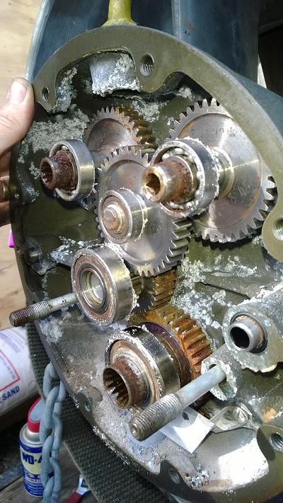 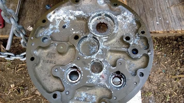 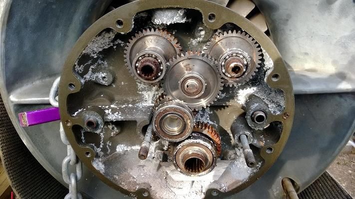 |
|
|
|
Post by finiteparts on Mar 2, 2014 14:27:55 GMT -5
Man that is a bummer on how much corrosion happens in these gear cases. Mine was not that bad, but it took a bunch of work to clean up the oxide formation in the case. The gears had a small amount of rust that I was able to clean off, but I am a bit concerned that a pit or other surface defect from the corrosion might cause a stress concentration or a rapid fretting of the gear contact surface. My theory was to run it one time for a few minutes and then tear it down to inspect the change in the surface. Is the center gear ok? That one is the critical one since it has the internal splines for the quill shaft that connects the gear box to the compressor...those internal splines would be tough to replicate...so if it is ok, you could always find or get made gears to replace the other ones in the box. I actually wonder if as the oil in the gear case evaporated (for lack of a more correct term) and water got in (from moisture in the air condensing on the inside of the case) it didn't form a more caustic solution in there. The manual states to protect the aluminum or magnesium parts (I am not sure if the case is Al or Mg?) after cleaning off the oxide, use a solution of 10% chromic acid to 90% fresh water heated to 140 F. The corrosion must be removed and the paint near the defect must also be removed. Swab the affected area with cotton soaked in the solution and continue till it turns brown. Wash off the area with fresh water and dry. It will wipe the brown coating off, but the surface has been protected. For magnesium, you must also prep a solution of one part manganese sulphate and one part sodium dichromate (or potassium dichromate)in ten parts fresh water (by weight). The solution can be heated to 180 F to increase the speed of reaction. Swab the area for 15 mins and rinse/dry as before. The long term storage of the engine was supposed to be preceded by draining all the oil and filling with one part MIL-C-6529 Type I (corrosion preventative) with three parts lube oil, or just a 100% MIL-C_6529 Type III. But, since many of these engines were donated to tech schools, for all we know, the students filled them with Pepsi or bong water...so now we have this mess. I have heard that muriatic acid might clean that tough oxide, but I haven't tried it yet. The home brewed fuel control might be a good choice, now that I see the gearbox. It should be relatively easy to make as shown in the manual. Here are a few pics...note that the specs are for the R-24 version, but I think they are the same for my R-3 and hopefully your R-12. Sorry that they are a bit out of order...  Look at the SFC number! We might be just as efficient if we dumped gallon jugs of kerosene into an open tube!!!! hehee!      |
|
|
|
Post by racket on Mar 2, 2014 16:18:26 GMT -5
LOL.......that Specific Thrust figure of ~38 lbs/lb mass flow is worse than a turbo based DIY engine , undoubtedly due to the very low Pressure Ratio ................yep, dump gallons of kero into her :-)
Cheers
John
|
|


 ? But I wonder if that might simply worsen the risk by deflecting rather than absorbing the high-energy parts. Your thoughts?
 for starting.