|
|
Post by racket on Oct 6, 2014 1:26:04 GMT -5
Hi Anders
Back on page 126 you posted some temps from during the test where the nut came off , you had a TOT of ~675 C at 1 bar P2 now you're up to 750 C with the same jet nozzle , but you were at 675 C with an open pipe , are you certain you had the jet nozzle installed for the earlier "nut loose" test ??
It could be the NGV as your earlier "loose nut" test was running a lot higher temperatures than I was.
If you check the comp clearance and its down under 0.3mm with the shaft pushed forward to take up the axial thrust clearance , it should be OK ...............at low P2 pressures, where some of your highest temps are, the "leakage" problems with comp clearances would be minimal compared to at higher rpm/pressures .
With the comp checked out OK , you may need to look at things "inside" , maybe check the individual injector flows by running pressurised fuel through them and collect the discharges into 18 bottles to verify equal flows , if they're OK then we can rule out the possibility that your thermocouple is measuring a "hot spot" .
Then its time for the NGV, and a good measure up to check flow areas and gas angles .
The one "good??" thing to come out of these test is the fact you can pretty much rule out the freepower stage for causing those previous high temps during the road test , 675 degrees C with an open pipe is way too high , it should be down in the low 500s .
One thing at a time , we'll get it sorted :-)
Cheers
John
|
|
|
|
Post by Johansson on Oct 6, 2014 4:59:14 GMT -5
Hi John,
The test where I dropped the compressor wheel was made with the 89mm jet nozzle attached, here is the video of the test:
With a <0.3mm compressor clearance the tips will rub the housing if pushed to the side without oil pressure, but this is ok I guess since the bearing tolerances are within specs.
Unfortunately I haven´t logged any fuel pressures, if so I could have checked if I need higher fuel pressure to maintain the same revs and that would have indicated a syringe blockage.
I will remove the fuel ring and flow test it, this means a complete disassembly of the engine but then I can do a closer inspection of the combustor and measure up the NGV properly at the same time.
Cheers!
/Anders
|
|
|
|
Post by Johansson on Oct 6, 2014 14:41:09 GMT -5
I´ve made some different charts from the numbers gathered during the two tests, test Nr 2 differs from Nr 1 by having a 89mm jet nozzle at the end of the 100mm diameter exhaust bend. (and test nr 1 didn´t have a P2 probe) 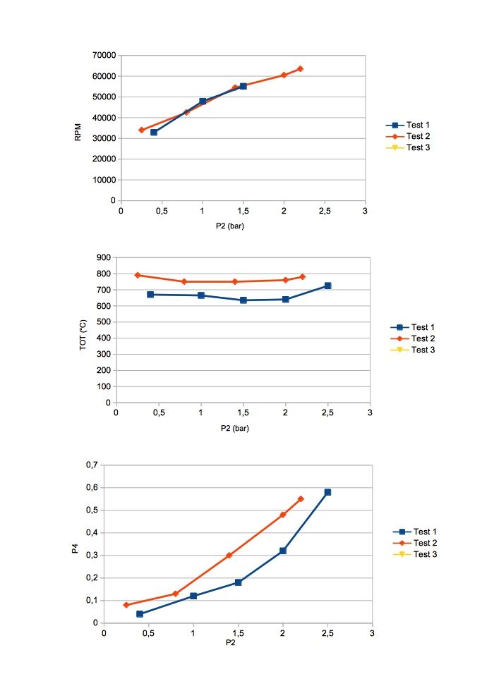 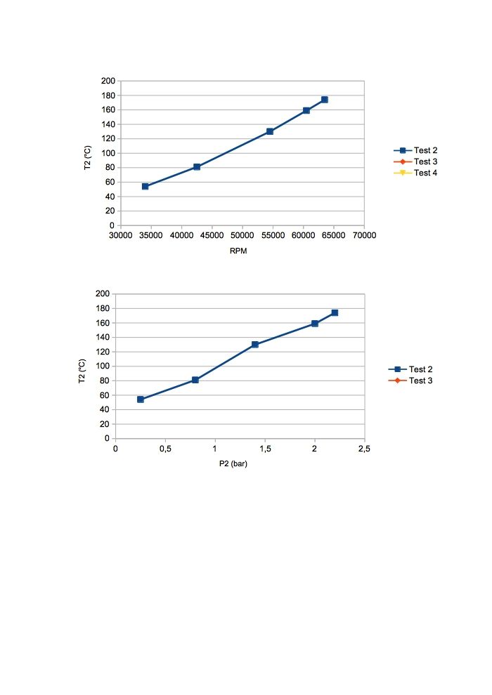 Cheers! /Anders |
|
|
|
Post by racket on Oct 6, 2014 15:49:23 GMT -5
Hi Anders
Thanks for the video Link .................she was purring nicely 'till the nut came loose .
Yep, too much temperature variation between those runs, though the first was with "cold" air , but the extra mass flow would have produced more backpressure which then should have "restored" temperature....................a good look inside is needed , check everything, one step at a time, starting at the front and moving back.
We can get away with a bit more radial clearance at the comp inducer , but the axial clearance at the exducer tips needs to be kept to a minimum, but you will need to allow enough clearance so that the wheel can't contact the housing if you force the wheel both radially and axially to the limits of bearing clearance, a bit of a rub might see the nut loosen again :-(
I just checked my build data for the FM-1 engine and I've noted that I used 3 thicknesses of 0.005" thick masking tape ( 0.015" total) attached to 4 comp exducer tips to check my axial clearance, so 0.4mm should be OK ............can you check that the comp housing hasn't "relieved" itself after its numerous heat treatments with each spoolup and perhaps has the comp running not quite true to its shroud . ..............several marking pen marks on the shroud and some masking tape on the comp blades and a quick turn or two will soon show up any out of true clearances .
I like the graphs , nice way to check run differences :-)
Cheers
John
|
|
|
|
Post by Johansson on Oct 7, 2014 0:29:48 GMT -5
Hi John, I will remove the engine from the chassis tonight and start going through everything, I´ll do a "backwards blueprinting" writing down every measurement since the original drawings were just something I used as a guideline so the final tolerances were decided on the go so to speak...  Something I noticed was that the fuel ring made out of hydraulic tubing with silver soldered syringes looked like shit on the surface last time I pulled the lid, perhaps the zinc coating don´t like the heat soak after shutdown? If the ring looks the same on the inside I assume I´ve got one or several needles blocked. How much do you think the 90 degree bend restricts the exhaust flow? Can it be so that the engine simply is running with a much larger restriction now than when I bench tested the engine with the short 89mm nozzle attached? Cheers! /Anders |
|
|
|
Post by racket on Oct 7, 2014 3:11:17 GMT -5
Hi Anders
The 90 degree bend will add some restriction but its a fairly large radius bend , I can't see it adding 100 degrees to the TOT , having said that , Andrew is having high temps from the 10/98 engine with a small radius bend and exhausting to atmosphere without a nozzle.
You might need to do some more bench testing of the engine if you can't find any obvious problems when you "blue print" her .
Cheers
John
|
|
|
|
Post by Johansson on Oct 7, 2014 4:01:20 GMT -5
Hi John, I´ll keep on testing the engine until I get the temps in order, at least the bearings are behaving nowadays. I´ll check the clearances for the compressor and turbine and adjust them to the values we discussed earlier via email, measure the diffusor and NGV sections and check the fuel ring for blockage or leaks. I will also fit a second temp probe to the exhaust pipe to see if I´ve been measuring at a local hot spot. After that I run the engine again with the 89mm nozzle removed to get the temps down a bit. Sounds like a plan? Cheers! /Anders |
|
|
|
Post by Johansson on Oct 7, 2014 10:12:17 GMT -5
I´ve just watched the GoPro video from the first gas producer test without the 89mm nozzle and I noticed that while idling the temperatures kept creeping higher and higher. After throttling the engine and falling back to a 0.4 bar idle the TOT falls off initially but slowly start creeping higher and higher from 650°C up towards 700°C.
Isn´t that a bit strange? I figure that even if the idle temps are unusually high they should at least be stable and not increasing like this, after throttling again the idle temp starts low and increases so the phenomena happens time after time.
|
|
|
|
Post by smithy1 on Oct 7, 2014 14:05:24 GMT -5
Hi Anders, You could indeed be having "hot spot" issues, a dual thermocouple is a really good idea, John had already done this to the 6041 Go-kart I now have, I see only minor temp variations between them of ~10-20C. Even when the exhaust is cold and with just the sun shining on one side I get quite a large difference in temps between the two sensors.  I notice on my small micro turbines, most of them have a hot spot @ ~5 o'clock as viewed from the rear, at first I thought it was just a "one-off" phenomenon but as I played with more and more micro turbines I noted that they nearly all had a similar hot spot, the reason for this is unknown to me  . Needless to say I now fit the thermocouples to the 11 o'clock position  . Be sure to take plenty of photos for us during your work please....I really enjoy looking at your photos, some of your ideas are very interesting and useful to the rest of us, I've learnt plenty from everybody's work. Cheers, Smithy. |
|
|
|
Post by Johansson on Oct 7, 2014 16:41:47 GMT -5
Hi Smithy, Interesting, 5 o´clock is almost exactly where I have my temp probe sitting. I´ll fit a second one opposite it to see if it reads a different temp. 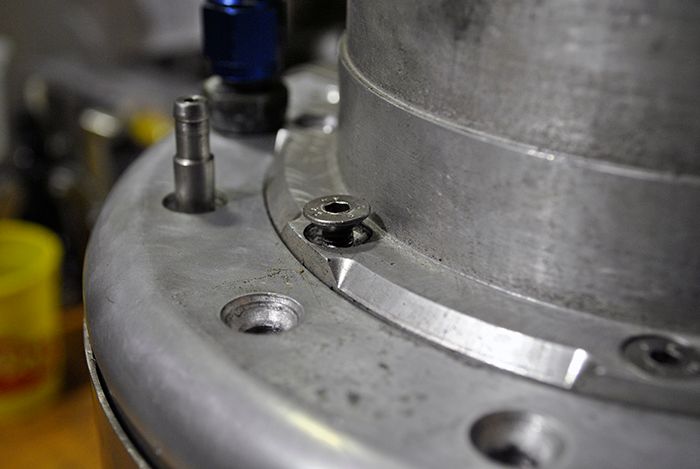 I removed the compressor housing today to measure the tip clearance, and I might have found a reason for the high temps. According to an earlier discussion with John I should aim for a <0.5mm radial clearance at the inducer that narrows down to a <0.12mm axial clearance at the exducer tips. 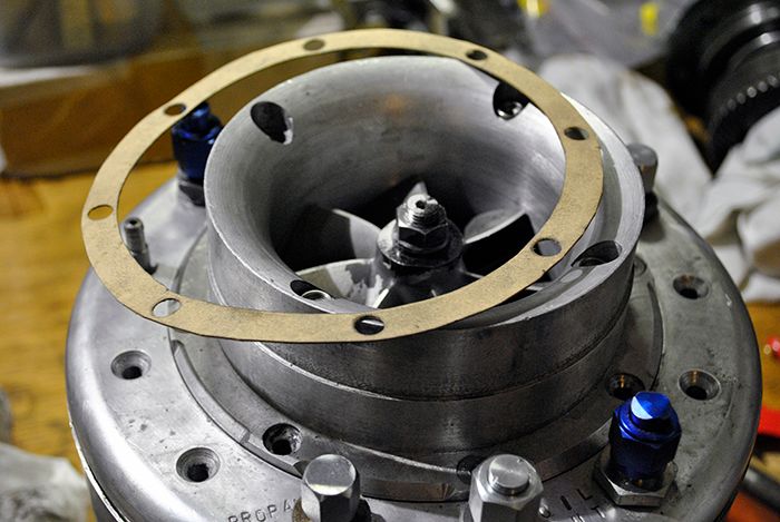 To get the exducer clearance down to 0.2mm (tightest I could get without blades rubbing when comp wheel was pushed radially) I had to fit a 0.25mm thinner shim behind the compressor cover, this means that I was running the engine with a 0.45mm exducer tip clearance. Almost 4 times what John recommended... 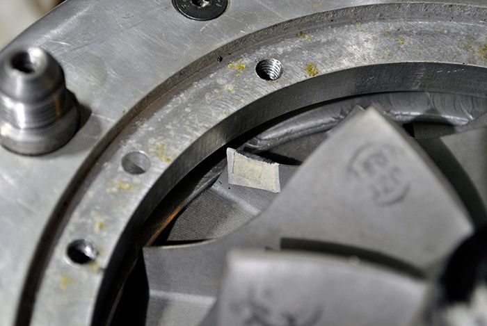 I also checked the turbine wheel clearance and it was ok after I fixed a slight misalignment between the turbine and the housing center. Since the compressor clearance was so badly off I´ve decided to run the engine again before taking it apart completely, then I will know how much it has affected the temperature profile of the engine. The thicker shim was fitted before the second ever run when a prolonged preheat heated the shaft so the compressor wheel rubbed its housing. If you look at the maiden run where I ran a tighter tip clearance the engine was idling at 600°C with a jet nozzle fitted (before the turbine wheel started rubbing the NGV plate and I had to shut the engine down). Despite major air leaks and badly designed internal air deflectors the engine idled colder than it does now after years of modifications. I think I am on to something here... Cheers! /Anders |
|
|
|
Post by racket on Oct 7, 2014 17:04:19 GMT -5
Hi Anders
I think you've got a malfunctioning gauge/thermocouple , its not following the throttle inputs all that well, but drops back very quickly .
It might pay to get a better setup with twin thermocouples as Smithy suggested , I've been using YCT brand YC-821 unit with sheathed K type thermocouples , the two temperature readings are always within 10-20 degrees of each other on the test stand .
I've used a number of different TOT setups over the years which have produced some inaccurate readings , I once had 4 thermocouples in the one jetpipe and all were at different temps , some quite large, but since changing to the YCT unit, numbers have been pretty close, well within the slight variation caused by minor differences in fuel flows to segments of the engine .
Cheers
John
|
|
|
|
Post by racket on Oct 7, 2014 17:39:43 GMT -5
Hi Anders
I was just looking through some stuff and found the radial clearance on the GT 60 turbo comp inducer was 0.015" , and 0.030" radially on the turb exducer .
Cheers
John
|
|
|
|
Post by Johansson on Oct 7, 2014 23:07:10 GMT -5
Hi Anders I think you've got a malfunctioning gauge/thermocouple , its not following the throttle inputs all that well, but drops back very quickly . It might pay to get a better setup with twin thermocouples as Smithy suggested , I've been using YCT brand YC-821 unit with sheathed K type thermocouples , the two temperature readings are always within 10-20 degrees of each other on the test stand . I've used a number of different TOT setups over the years which have produced some inaccurate readings , I once had 4 thermocouples in the one jetpipe and all were at different temps , some quite large, but since changing to the YCT unit, numbers have been pretty close, well within the slight variation caused by minor differences in fuel flows to segments of the engine . Cheers John Hi John, It has indeed been acting strange sometimes, but I have two sets and when swapping them I get the same result. To make sure I will use the digital meter I used for TIT readings (didn´t work since the probe melted...) and measure TOT with, I can even fit both of the analogue meters plus the digital one to have one probe every 120° around the jet pipe. To get the best sound for the video I use the sound from the hand held camera and the picture from the GoPro camera, I have tried to sync the two as close as I can but there might be a .1´th of a second of lag. Even with the original sound the temp is a bit slow to react during startup so there might be a problem with the probe after all. The temp probe Ernie suggested might be worth a try, I can find them on Ebay for 10 euros each. www.newfrog.com/p/2m-egt-thermocouple-k-type-exhaust-probe-high-temperature-sensors-screw-threads-21267.htmlCheers! /Anders |
|
|
|
Post by Johansson on Oct 7, 2014 23:08:28 GMT -5
Hi Anders I was just looking through some stuff and found the radial clearance on the GT 60 turbo comp inducer was 0.015" , and 0.030" radially on the turb exducer . Cheers John Hi John, Do you know what the axial clearance was set to? Cheers! /Anders |
|
|
|
Post by racket on Oct 7, 2014 23:35:34 GMT -5
Hi Anders
Nope , not sure what the axial exducer clearance was , but I'd imagine it would be similar , the main thing is that with clean dry bearings without an oil film ,nothing scrapes when the wheel is forced across and pulled forward at the same time , we need a bit more clearance than an engine with "rigid" ball races just in case the rotor dynamics start to wobble the shaft around in our "sloppy" brass bushes.
Those thermocouples look good , nice price , can you use the same fittings at the receiving unit ?? .................my thermo unit has those twin flat pin setup .
Cheers
John
|
|


 . Needless to say I now fit the thermocouples to the 11 o'clock position
  .
.

