ripp
Veteran Member
 I'm sorry, I don't speak english, so I torment you (and myself) with a translation program,Sorry
Joined: January 2013
Posts: 236
|
Post by ripp on Oct 15, 2014 16:13:59 GMT -5
Hi Anders
please also some pictures from the outside of the combustion chamber (colored)
regards
rip
translate.google.at
|
|
|
|
Post by racket on Oct 15, 2014 16:34:20 GMT -5
Hi Anders
Yep, take Smithies advice about checking the piston ring seat for roundness , I found that my stainless NGV wall bore where the ring seated "shrunk" a tad after some run time , the metal's "heat treatment ??" probably relieved/induced some stresses .
To skim out the seating I just turned up a boss in the lathe to simulate the shaft tunnel, then bolted the NGV to it, that kept everything nice and true , easy job :-)
Cheers
John
|
|
ashpowers
Veteran Member
Joined: February 2011
Posts: 207
|
Post by ashpowers on Oct 15, 2014 18:20:50 GMT -5
Hi Anders,
Man, I have to say, the state of your combustor and turbine, knowing how much time you have on it, is quite impressive my friend. =)
I would really like to see more pictures of the combustion chamber from several angles with the idea of taking the hole placement/hole size into account for a redesign of my combustor when I get to that point in my project. Your setup is obviously working very well and I commend you for that! =)
As always, keep up the great work my friend!
-Ash
|
|
|
|
Post by racket on Oct 15, 2014 21:12:42 GMT -5
Hi Anders
Before you start blocking off NGV passageways I feel we might need to look at a couple of other things.
Just thinking out loud here .......
Your evaporators look like they've been pretty hot , maybe a bit hotter than "ideal" , could there be a slight restriction to airflow going into the evap , I have a bellmouthed inlet on my evaps as well as "D'ing" along the tube to promote turbulence and hopefully "cooling??" of the evap as the fuel is evaporated .
If theres was a minor combustion "problem" at idling conditions it might be producing abnormal temperatures which then correct themselves as the combustor air pressures go up resulting in your TOTs then going down .
What fuel are you burning ??
I'm not too concerned about your current temps having looked at the NGV and turb wheel , and I don't think your ~10% bigger NGV throat areas is a problem considering your cold climate which should produce more mass flow, we've been designing for a max T I T of 900C which is still fairly modest for a "short life" engine , the AiReseach engine from the 1970s was running nearly 140 C degrees hotter for a maximum .
One other thought I had was , thrust bearing friction , have you measured your torque drag under full oil pressure, I think I had ~0.5 foot pounds of drag , it took a good push with the finger to get the comp to move .
Cheers
John
|
|
ashpowers
Veteran Member
Joined: February 2011
Posts: 207
|
Post by ashpowers on Oct 16, 2014 2:46:39 GMT -5
John, in one of the recent videos showing a testrun, when the oil pump was turned on it was producing somewhere around 6 bar of pressure which was of note. I dont know if higher oil pressure results in a difference in drag within the thrust bearing and/or the main shaft bearings or not. Thinking about it, I dont see how it would affect rotating friction at all since any change in oil pressure really only dictates flow quantity. If anything, there is a small increase in rotating friction at higher oil pressures simply due to the fact that there is more oil quantity moving through the bearing tolerances and it will heat and thin out less just due to the difference in its dwell time... and this would be a negligible difference I am sure. As for the main bearings, they receive oil via a 180 degree slot cut into the bore but when the group is rotating, the hydrodynamic "floating" force of the bearings on the oil film are much stronger than the hydrostatic oil pressure that pushes the bearings away from the delivery port. This would result in a drag force not much different than what you would see when rotating the group without any oil pressure being applied. Trying to measure drag force on the group with it at a standstill and oil pressure applied, it will show higher resistance simply due to the fact that the main bearing's delivery ports are going to force the opposing side of the bearing into the face of the bore as well as the face of the shaft into the opposing side of the bushing. I dont think a static friction test would really tell you anything about the resistance of the thrust bearing at all - the resistance to rotation would be coming from the main bearings-bore contact and shaft-bearing contact.
I've been looking around the web trying to find information on the relationship between oil pressure and drag for the radial bushings as well as for the tapered pad hydrodynamic thrust bearing configuration but haven't come across anything as of yet.. Even still, I have a hard time believing that the slightly elevated oil pressure he is running would really create any notable effect on the engine's performance. The drag forces created by this type of bearing support system already come with a given amount of drag to begin with and I would believe that these forces are considerably larger than the effect of the ~doubling of oil pressure he is running at.
|
|
|
|
Post by racket on Oct 16, 2014 3:28:52 GMT -5
Hi Ash Our TV94 thrust bearings only have lube pressure supplied to one side , unlike the more modern method of having lube pressure to both side of the rotating face/s , by having it only to the "front" side where the axial thrust goes to when under high air loads , at low air loads the oil pressure is forcing the rotating part hard against the rear buffer bearing that doesn't have any balancing lube pressure My GT6041 turbo would rotate several times from a flick of the finger on the comp blade even under full oil pressure , the TV94 needs to be forced around , theres no "several revolutions" , it stops when you stop pushing :-( ...............thats why I needed a car starter motor running on 24 volts to spoolup my 10/98 engine jetandturbineowners.proboards.com/thread/19/10-98-engine?page=4Do you think a 360 degree oil supply groove for the brass bushes might improve the situation somewhat ?? .............I currently only have a single oil hole for each bush , no groove of any sort, I don't know what the original setup is for the TV94 . Cheers John |
|
|
|
Post by Johansson on Oct 16, 2014 5:46:57 GMT -5
Hi Anders, I wouldn't call it a "Big F@#k-up". She looks pretty good in there, not much in the way of burnt or bent bits.! The shaft bearing surface looks good too, no real heat soak evidence on the shaft either...I think that's further evidence of the TIT's being in the "OK" range, if the TIT's were too high we'd see some "blue-ing" of the shaft. It might pay to check the "roundness" of the oil ring sealing face in the rear housing, might be where the oil is getting through, do you have a new/spare ring to use? Or possibly the a high differential between oil pressure vs the pressure at the back-side of the turbine. Cheers, Smithy. I was expecting more signs of overheating since the engine must have been running with TIT´s near 1000C several times, it must be a sturdy design.  I will check the roundness of the seal bore, I haven´t seen any signs of leakage earlier so it feels like something has happened during one of the later runs. Hi Anders please also some pictures from the outside of the combustion chamber (colored) regards rip translate.google.at I try to take some pics tonight, I don´t think that there is much to read from the heat pattern though after several hot starts, prolonged preheating etc. Hi Anders, Man, I have to say, the state of your combustor and turbine, knowing how much time you have on it, is quite impressive my friend. =) I would really like to see more pictures of the combustion chamber from several angles with the idea of taking the hole placement/hole size into account for a redesign of my combustor when I get to that point in my project. Your setup is obviously working very well and I commend you for that! =) As always, keep up the great work my friend! -Ash Thanks a lot Ash! I´ll post some more pics of the chamber here as soon as I can. The combustor design is all John´s, so he is the mastermind behind it and I am merely the sheel metal basher. Hi Anders Before you start blocking off NGV passageways I feel we might need to look at a couple of other things. Just thinking out loud here ....... Your evaporators look like they've been pretty hot , maybe a bit hotter than "ideal" , could there be a slight restriction to airflow going into the evap , I have a bellmouthed inlet on my evaps as well as "D'ing" along the tube to promote turbulence and hopefully "cooling??" of the evap as the fuel is evaporated . If theres was a minor combustion "problem" at idling conditions it might be producing abnormal temperatures which then correct themselves as the combustor air pressures go up resulting in your TOTs then going down . What fuel are you burning ?? I'm not too concerned about your current temps having looked at the NGV and turb wheel , and I don't think your ~10% bigger NGV throat areas is a problem considering your cold climate which should produce more mass flow, we've been designing for a max T I T of 900C which is still fairly modest for a "short life" engine , the AiReseach engine from the 1970s was running nearly 140 C degrees hotter for a maximum . One other thought I had was , thrust bearing friction , have you measured your torque drag under full oil pressure, I think I had ~0.5 foot pounds of drag , it took a good push with the finger to get the comp to move . Cheers John I am not sure if I could fit a bellmouthed entry for the tubes, but it might be worth a try. I am tempted to change the tube material to something a bit more heat resistant just to be on the safe side, and then I could add a radius to the air entry. I am running the engine on JetA1, earlier I used pump diesel but a friend sent me a barrel of kerosine which I have been using since the first run with the engine in the frame. Bugger, and I was so glad that I´d finally found the problem.  So let´s leave the NGV theory for now then, draggy bearings might very well be a problem since I need to use force to rotate the shaft under full oil pressure. There is no way I could rotate the shaft by grabbing the nut, I need to hold the inducer blades to do that. Ash´s journal bearing groove idea is very interesting, a single hole from one side will as he say push the shaft to the opposite side while a 360 degree groove would eliminate that problem. I am still fairly sure that the thrust bearing is the one that causes most drag, but since you are using the same bearing assembly as I you should logically have suffered the same temp issue if that was the problem. Cheers! /Anders |
|
ashpowers
Veteran Member
Joined: February 2011
Posts: 207
|
Post by ashpowers on Oct 16, 2014 11:08:20 GMT -5
HI John,
Ah, I Did not know that the thrust bearing was single-faced. High oil pressure in that case would explain greater drag. What oil pressure were you running your engine at?
In all of the journal bearing center housings where the bushings ride, the delivery port is a slot that appears to be cut by a wheel with an o.d. the same as the bore i.d.. This "cutting disc" moves directly in line with the oil feed port and carves out a slot to deliver oil to the bearing and covering 180-degrees of its circumference. The width of the slot is the same as the width of the holes in the brass bushing. I really dont see why it would be a problem to do that all the way around the bearing but as I said, once the bits get spinning, the hydrodynamic lift of the difference in rotating speeds of the various faces will float the entire assembly. That may not be the case with 6 bar of oil pressure pushing out through a single hole, not to mention, the bushing also has its own holes. I gotta imagine that the effect of a single feed port into that kind of bearing arrangement is going to cause some type of resonance at various critical speeds as that oil pressure is momentarily forced through the holes in the bushing as it passes the oil delivery hole in the housing. A slot will eliminate that from being an issue though.
|
|
|
|
Post by Johansson on Oct 16, 2014 12:54:35 GMT -5
If the spare turbine wheel I bought from Andrew was identical to the one in the 10/98 I think I know what is causing the temps. I compared the wheel I´ve been using to the spare wheel, and my wheel is "clipped" so the exducer angle is close to 30° from axial while the spare wheel exducer angle is 40-45° (didn´t have time to measure exactly since I was supposed to be baking a cake while my feancee was doing an errand).  The spare turbine fits the housing just fine so it must be made from the same casting, just the machining that is made differently. By the way John, the burnt oil marks on the turbine blades were very easy to scrape off with a fingernail. 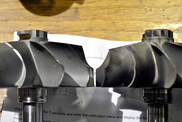 I´ve also managed to take a bunch of pics on the combustor, if there is any particular view you want just let me know. Bottom side: 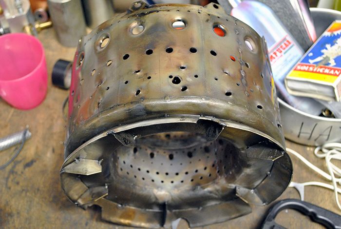 Left side: 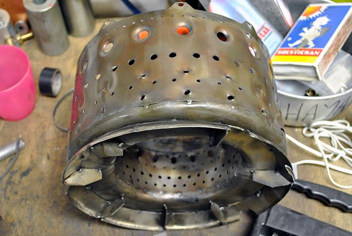 Top side: 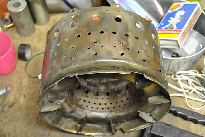 Right side: 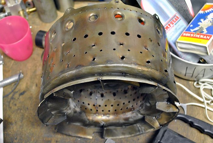 Inside: 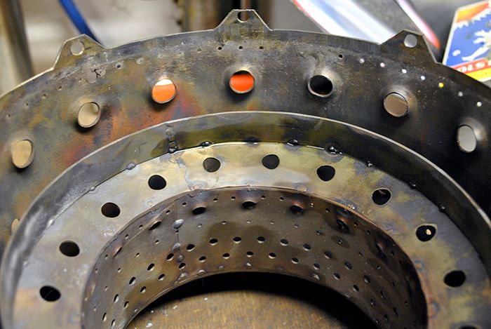 Here you can see marks from where the vapor tube injects the fuel into the chamber:  Finally a pic of the combustor cap, no signs of overheating. 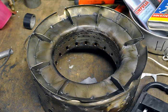 Cheers! /Anders |
|
|
|
Post by racket on Oct 16, 2014 15:49:05 GMT -5
Hi Ash
Yep , we run a 360 degree thrust bearing , its nice and big as well, so no worries about it at full power.
We have been thinking of trying to pressurise the "buffer bearing" on the other side so that theres a balanced lube force on the rotating section,...... I've heard that some of the turbo guys have been "experimenting" with modified thrust bearings .
I was running up to 70psi oil pressure with cold 10 deg C oil , which dropped to 40psi when pretty hot , this was my Hobbs switch cutoff pressure point for the fuel pump , oilpump pressure relief was ~50psi , but cold oil "overpowered" the pressure relief flow passageway resulting in the 70psi oil pressure with cold oil and engine .
I based my single hole oil supply to each bearing on a scrap Garrett truck turbo I had , maybe the bigger/slower turbos don't need the same lube distribution system as the smaller ones , I'd really like to see inside a TV94 bearing housing to check its setup , a more modern GT variety might be different .
Cheers
John
|
|
|
|
Post by racket on Oct 16, 2014 16:14:46 GMT -5
Hi Anders
What material are you using for your evaporators ??
Your flametube is still looking in very good condition :-)
Clipped wheel ..........I used those Garrett wheels for my early engines without problems , even the initial runs with the 10/98 which had good temps ,until I replaced it with the unclipped wheel after the flametube malfunction when I changed to the Rotomaster wheel , theres ~0.150" less axial clipping at the tip , and still has the same ~10 degree exducer OD taper, strangely enough it still has the Part Number as the Garrett wheel
Tip height appears to be a tad bigger at ~20mm , there could also be a slight difference in the exducer diameter, theres ~7% less flow area through the exducer blades , but ~5 degrees more deflection at roughly the mid flow region of the exducer , its probably a better wheel for a 2 shaft engine as the extra deflection produces more power requiring less pressure drop so slightly lower gas velocities needed out of the exducer to produce the required deflection.
Cheers
John
|
|
|
|
Post by smithy1 on Oct 16, 2014 16:40:29 GMT -5
Hi Anders, There's something seriously wrong with your CC.....it's got no burnt or melted bits..! As John says..."BORING".  Looks to be in good condition...which again points to good combustion and favorable TIT's. I still believe you'd see evidence of excessively high TIT's on the leading edges of your NGV and turbine inducer blades...and your turbine wheel looks fine. |
|
|
|
Post by racket on Oct 16, 2014 17:05:41 GMT -5
Hi Smithy
Yep, I'll go along with you there , the engine looks remarkably "untouched" by excessive heat .
The fact that the "black oil marks" on the turbine wheel were easily scrapped off sorta points to the turb wheel temps being kinda low , if they were hotter, the "black" would soon become "hard brown" or vapourised completely and the wheel metal being a "strange" colour .
I'm leaning more towards those thermocouples/gauges not registering the correct temps , I think I'd be getting the setups checked by someone to calibrate them .
When I was doing development work on the TV84 bike engine I tried measuring T2 with a thermocouple in the delivery tube between comp and combustor , I could never seem to get it to work despite testing the setup in boiling water etc etc for accuracy , in the end I put it down to the high speed airflow creating "gremlins" that upset the electrics of the thermocouple ..........strange things can happen :-(
Cheers
John
|
|
|
|
Post by smithy1 on Oct 16, 2014 20:29:54 GMT -5
Hi John, Do you think those hand held "infra-red" type thermometers are any good?? Something like this one: www.amazon.com/GSI-Professional-Non-Contact-High-Temperature-Thermometer/dp/B0053YE6ZIWe often used them to good effect on the headers of the Top Fuel Dragsters as the car was idling before going into the stage lights, we used them to check for dead cylinders, Mind you....with the amount of nitro fuel going through those engines, it's a wonder they ran at all..! I guess 88amps via twin spark plugs will do that for you..! Cheers, Smithy. |
|
|
|
Post by racket on Oct 16, 2014 22:56:57 GMT -5
Hi Smithy
I'm not a great fan of IR thermometers for our turbine use , guys have used them for measuring scroll housing temps but they'll always be under measuring the actual gas temps , they have their place for jobs like finding a dead cylinder , but I think we're better off with the more conventional thermocouple fitted into the exhaust stream , it'll be measuring not only the static gas temperature but also a fair percentage of any dynamic temperature as the gases impact the thermocouple , this then makes it a little more accurate when doing calculations for jet nozzles or freepowers
If the IR thermometer could be trained onto the turbine wheel area itself , then they have a better chance of getting a more accurate reading , but measuring the temp of a wall where heat transfer rates and external cooling are unknown is fraught with possible inconsistencies .
Our TOT thermos are just so important I feel we need to spend a reasonable amount on them if we want to run our engines right up to their temperature limits , replacing a turbine wheel is going to cost a lot more than probably the most expensive digital thermometer , a good quality digital unit which complies with an industry standard for accuracy, coupled to a pair of compatible K type sheathed thermocouples is cheap insurance .
When I first built my TV84 engine I used a fairly expensive 3" VDO EGT gauge and thermocouple ,but turb scroll "colour" didn't match the gauge readings , there appeared to be a large under read, then I added a digital gauge and large sheathed thermocouple , but still had "inconsistent" readings , so added an EGT gauge and thermocouple made for an ultralight aircraft ...............still had inconsistent readings between the gauges , up to 100 C degrees ...........it was very frustrating ...........it would have been cheaper in the long run to have paid out for a calibrated unit early in the development and had the peace of mind to go with it, as not knowing our actual temps is a big worry when things start to "glow" .
Cheers
John
|
|


 Looks to be in good condition...which again points to good combustion and favorable TIT's.