|
|
Post by racket on Jan 3, 2011 18:12:43 GMT -5
Hi Anders
Scavenge pumps need to be several times the capacity of the supply pump , those TV94 brass bushes need maybe up to 10 litres/min with hot thin oil at a decent pressure , so the scavange pump probably needs to have 30-40 lpm capability to handle the frothy air/oil mix.
Cheers
John
|
|
|
|
Post by Johansson on Jan 4, 2011 14:27:01 GMT -5
I´ll do a flow test of the scavange pump this week to find out how well it performs.
|
|
|
|
Post by stoffe64 on Jan 5, 2011 1:32:42 GMT -5
as i remembered about that particular pump is that it was originally designed to pump diesel fuel OR water at a flowrate of around 12-14 liters per minute, with oil i think it will be less than that, perhsps you can use two pumps to increase the flow Anders?
best regards/stephan
|
|
|
|
Post by Johansson on Jan 6, 2011 14:42:53 GMT -5
Hmm, not more than that? Well, I´ll just have to try and see how it works and if it can´t handle the flow I will have to build some sort of gear pump. I made some progress on the engine today. I followed Racket´s advise on increasing the bleed air flow, I opened the two 2mm holes up to 3.5mm which is the same total area as 6x2mm holes and made a pocket closest to the shaft which the air can fill up and keep the combustion away from the shaft. 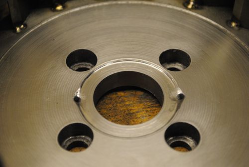 I also added four more fastening bolts in the compressor cover just like Racket suggested earlier, now it has eight countersunk bolts which should be plenty. Forgot to take any pics of the finished piece though, sorry about that.  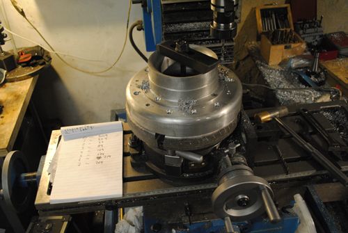 My last job today was to drill the 18 vapour tube holes in the turbine housing. 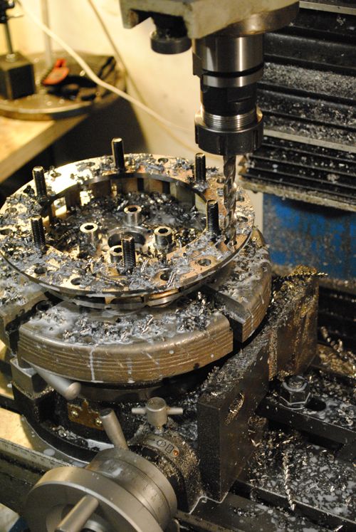 This is what it looks like without all the metal scraps (what is it called in english?). 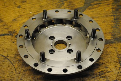 I made a 100mm long test tube and pushed it in place, I can´t weld them until the rest of the turbine housing is finished since I won´t be able to fit it in the mill anymore with the vapour tubes in place. 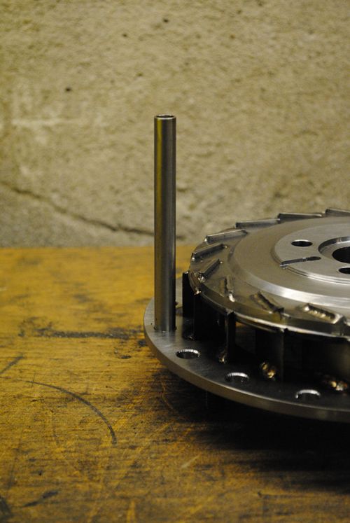 A picture of the entire engine assembled. 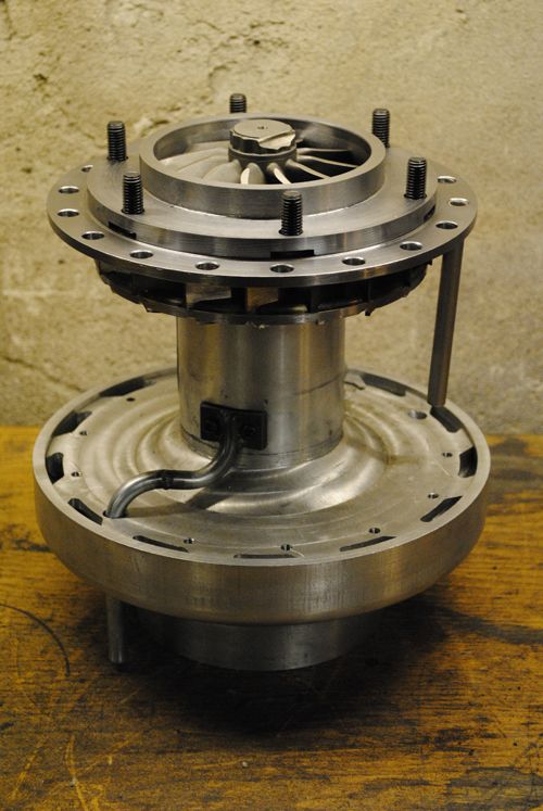 Cheers! |
|
jeta747
New Member

Joined: January 2011
Posts: 3
|
Post by jeta747 on Jan 7, 2011 7:50:31 GMT -5
Blimey! this is taking DIY turbines to another level. Very impressive and well done
Justin
|
|
|
|
Post by Johansson on Jan 7, 2011 9:17:24 GMT -5
Thanks a lot!  If the build keeps progressing like this I should have it ready for its first start this summer, can´t wait to hear it spooling up!  |
|
|
|
Post by racket on Jan 7, 2011 16:27:14 GMT -5
Hi Anders
Summer it will be :-)
You've only got a bit of "tin work" to go for the flametube and a bit of fuel plumbing.
Then you can start on the freepower once she's fired up
Cheers
John
|
|
|
|
Post by Johansson on Jan 7, 2011 17:12:46 GMT -5
Once I have a decent combustor design a friend of mine will borrow a cnc-plasma cutter at work and cut it out from a sheet of SS2333 for me, I will save both work and drills by not having to drill hundreds of holes in thin stainless sheet. When I am satisfied with the CC design I will order better material for it, ss2368 or inconel 600 but during the first experimental runs it will have to do with cheap ss2333. I cannot spend the entire paycheck on the engine, a man needs money for beer as well!  I am very tempted to try liquid preheating directly instead of going for propane, sooner or later I will have to change to liquid since I cannot fit a propane bottle to the bike and once I have sent the NGV away for cheramic coating it would cost lots of money to do it all over again after adding a couple of holes for the preheat nozzles. |
|
turborico
Member
 
Joined: December 2010
Posts: 24
|
Post by turborico on Jan 7, 2011 20:39:28 GMT -5
Will you be using an annular combustion chamber?
One thing I've been wondering about, why do most DIY gas turbines preheat their liquid fuels? All the APU's I'm familiar with simply atomize the fuel by means of a nozzle (or several, in the annular combustion chamber designs). I imagine the main reason is that it's probably pretty difficult to design a safe and effective fuel nozzle, but just speculation on my part.
|
|
|
|
Post by racket on Jan 7, 2011 22:33:01 GMT -5
Hi Rico
The use of evaporators means we can use low pressure fuel pumps like an auto EFI pump , we only need a maximum of ~20psi above combustor air pressure , so ~60 psi max fuel pressure , unlike at least 500 psi for a spray nozzle with similar "efficiency" ........................I use 18 straight "Jackson D tube " evaporators in my engines.
In my turbine bike engine I used high pressure spray , ~750 psi max pressure and a single Steiner hollow cone oil burner nozzle , but the high pressure pump requires high power to drive it , this is the reason its not commonly used by DIY'ers , suitable nozzles are easy to source .
Theres a number of aero turbine engines that have used evaporators , including those on the supersonic Concorde , evaporators can provide an advantage over spray nozzles in some applications .
Cheers
John
|
|
turborico
Member
 
Joined: December 2010
Posts: 24
|
Post by turborico on Jan 8, 2011 0:21:55 GMT -5
Good info, thanks John! I can't wait to see how this bike will turn out. Given the crazy stuff Anders has come with in the other projects, I think it'll be most impressive...  |
|
|
|
Post by Johansson on Jan 8, 2011 2:54:02 GMT -5
Thanks for the confidence!  |
|
|
|
Post by Johansson on Jan 10, 2011 17:55:31 GMT -5
I made the air deflectors today, another piece of knowledge Racket has payed dearly for that I get for free. Hats of to him for this, at least one major meltdown saved for me!  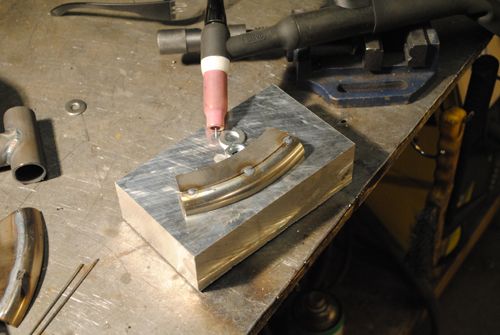 I will use bolts with less protruding heads to get more space for the combustor. 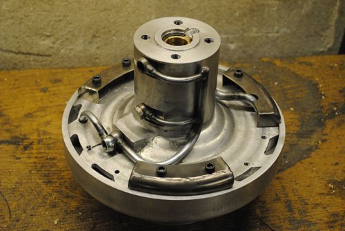 A closeup. They cover 6 out of 13 diffusor exits so I should get enough air on both sides of the combustor, the vapour tubes are fed from the outer side so that side got one slot extra. I can always add or remove deflectors later if I see heat damage on either side. 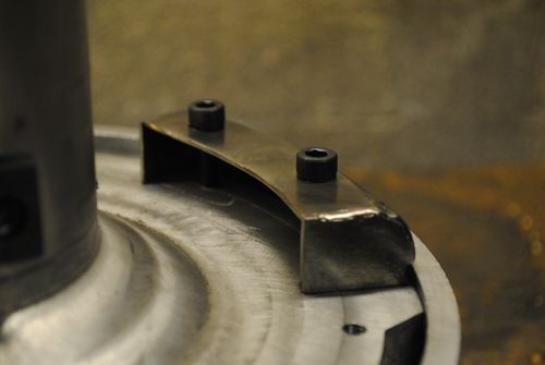 Here is a final picture of the full bolt circle in the compressor cover that I forgot to take earlier, I will mill away the sharp edge between the bolt heads later so it will look a bit better. 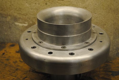 Cheers! |
|
|
|
Post by racket on Jan 10, 2011 20:02:50 GMT -5
Hi Anders
Lookin' good :-)
If I could make a suggestion , try and weld a couple more short radial "vanes" in each of the deflectors to eliminate any remnants of swirl , the deflectors will probably work as they are, but just to be on the safe side, some extra vanes will split the large duct into smaller segments for better control of the air .
Yeh, in your final assembly of the deflectors, flusher fitting screws will be needed , you'll need ever last millimetre of axial distance for the flametube , we need ~3mm clearance between the front cover over the flametube and deflector/screw heads to accomodate any excessive axial expansion of the flametube as can happen during a hot/bad start , 110mm flametube X 1,000 C degrees by 0.000022 = 2.42 mm .
LOL........Did you cut up some "kitchen ware" for those nice curved deflector segments ??
Are you fitting a sealing O'ring around the outside of the front alloy cover ??
Build coming along nicely ..........................you do such nice work :-)) ..............if only I had your skill level :-((
Cheers
John
|
|
|
|
Post by Johansson on Jan 11, 2011 1:07:56 GMT -5
Good pointer there, I´ll fit some dividing vanes inside them next time I visit the workshop. They will also serve as supports so the middle of the duct won´t bow down when the bolts are tightened. I lay awake last night thinking about the bolt head problem, perhaps I could make the heads flat and low in the lathe and put a weld bead on them to keep them in place after they are tightened. I can aways grind the bead away if I need to move them, and this way I will have a couple of things less inside the engine that can come loose. Ha ha, no kitchen tools sacrificed for this. I used a section of a spare steam tube from a military steam boiler that I bought a couple of years ago for a steam boat build. =) Yup, an O-ring seal around the diffusor cover edge. I don´t even think that I will need any bolts there since the cover will be held in place by the turbine cover bolts. Thanks! Your work is not exactly painful to look at either, you know.  |
|