|
|
Post by Johansson on May 8, 2012 15:38:01 GMT -5
I finished the oil pressure regulator today, it works like a charm without a drop of oil leaking anywhere. Wish I could say that more often...  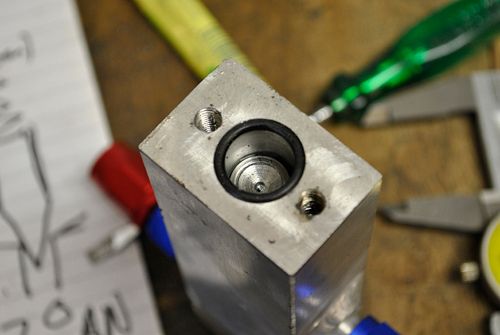 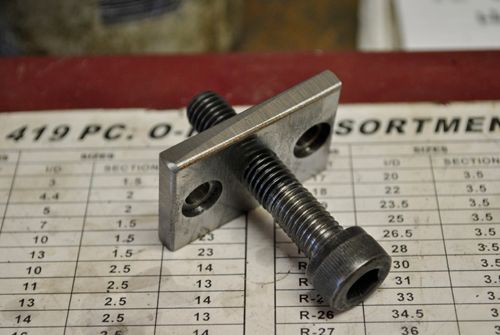 I made some special fittings for the new oil pump, when I fit the pump to the bike I will have a large AN coupling on the suction side instead of the hose fitting. 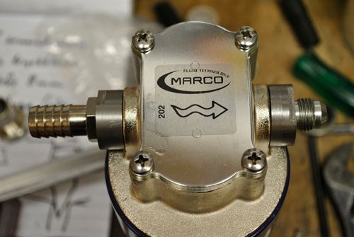 Here is a pic of everything hooked up for the test, I pushed the oil through a not-running scavange pump just to get some restriction for the oil pump to work against. 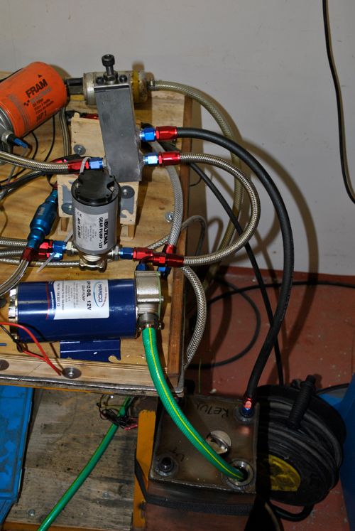 The oil pressure is very stable and spans from below 3 bar to above 5 bar, I didn´t dare to go higher since I would risk blowing a gasket in the scavange pump but it feels like I should be able to go a kg or two higher still. 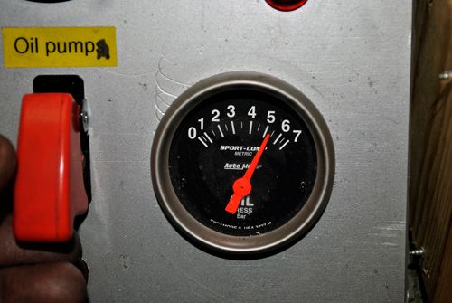 One step closer to the next test run! Cheers! |
|
|
|
Post by racket on May 8, 2012 18:55:00 GMT -5
Hi Anders
Mmmm 5 bar .....plenty :-)
Cheers
John
|
|
|
|
Post by Johansson on May 9, 2012 0:18:43 GMT -5
I figure I will need the larger capacity once I start bleeding off oil for the gearbox lubrication. |
|
|
|
Post by racket on May 9, 2012 4:26:25 GMT -5
Hi Anders
Yep , another couple of litres per minute , half for the gearmesh and the rest for the pinion bearings .
Cheers
John
|
|
|
|
Post by turbochris on May 9, 2012 21:31:43 GMT -5
did it get hot at 5 bar? did you measure the current draw?
|
|
|
|
Post by Johansson on May 10, 2012 0:02:58 GMT -5
I didn´t run it long enough to get hot, but the pump didn´t sound very strained at all.
No current measurements unfortunately, I will check the draw for the entire system later to know what size of battery bank I will need.
|
|
|
|
Post by Johansson on May 15, 2012 8:06:51 GMT -5
I´ve started to gather all drawings and calculations for the engine in a folder instead of having them scattered around the workshop and in my computer. 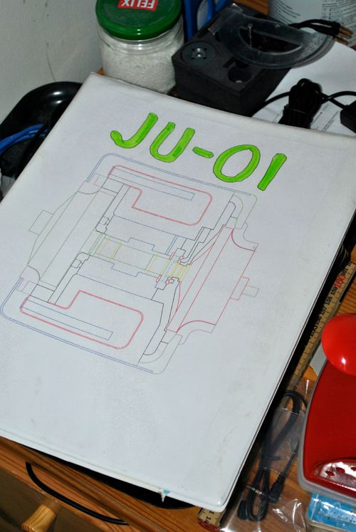 As if that wasn´t enough most of the "drawings" are only rough scetches that I partially ignored while making the parts for the engine so at some point I should take the engine apart and make a new set of drawings that actually looks like the finished engine... ;D 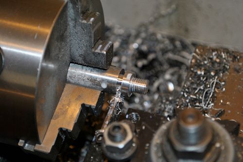 I´ve also made some AN4 plugs to seal the fuel and oil lines when not connected to the engine, until now I have used electrical tape but plugging them feels much safer. 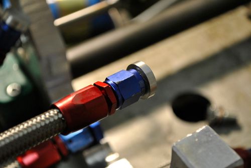 The compressor shim arrived today after having been sent to a friend for trueing in his grinding machine, now the surfaces are within 0.001mm so it should not cause any more imbalance from bending the rotor shaft. 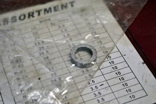 I have also got in touch with a very helpful guy that works with gear transmissions, he will do some research for suitable angle drive gears and get back to me. He didn´t even hang up when I told him about the 30.000rpm on the ingoing shaft so it is looking promising... Cheers! |
|
ashpowers
Veteran Member

Joined: February 2011
Posts: 207
|
Post by ashpowers on May 15, 2012 8:30:26 GMT -5
Hi Anders,
If you want to send me dimensioned drawings of your parts I could probably model them in solidworks for you. =) I think you are using the same turbine and comp as I am which makes things a bit easier.... even if not, I've gotten pretty good with the modeling and I just built a new CAD workstation last night - i7 quad core, 8gb ram, NVidia Quadro, 120GB SSD. This new workstation ..oo00--F-L-I-E-S--00oo...
|
|
|
|
Post by Johansson on May 15, 2012 9:09:15 GMT -5
I would if I had any, there is probably not a single drawing that looks 100% like the finished part...  Damn that is quite a CAD computer! |
|
ashpowers
Veteran Member
Joined: February 2011
Posts: 207
|
Post by ashpowers on May 15, 2012 15:14:32 GMT -5
On the next teardown, make good use of a set of calipers and angle finder and dimension her up. Even crude sketches will work, so long as the measurements are on the money I can build the model in short time.
I would really like to model your combustion chamber to see what kind of entry flow properties it shows. =)
|
|
|
|
Post by Johansson on May 18, 2012 16:30:09 GMT -5
Will see what I can do. I had some time to assemble the engine today so now it is standing in the test rig waiting for some jet fuel. Before I started assembling I figured out a way to lock the turbine housing bolts which has bothered me for quite some time, I used NordLock washers under the bolt heads and shaved some height off the heads in the lathe to get them in line with the top of the holes again. 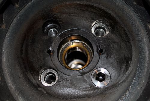 After that I assembled the engine again with lockwire and a well torqued down compressor nut. I must say that this is one hell of an easy maintained engine, I can probably take it apart completely and reassemble it in just a couple of hours without rushing things. Might come in handy some day at the salts when an oil gasket has blown. 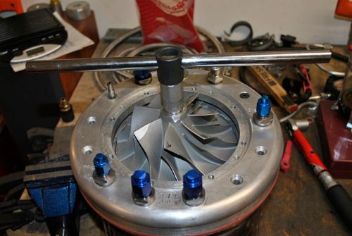 Assembling the turbine side. 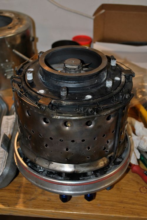 Making new oil hoses for the underpressure gauge that will fit on the suction line to one of the scavange pumps, I have done this so many times now that I don´t even bleed from my fingertips any more. Those pointy metal strands at the hose ends are very eager to draw blood from rookies... 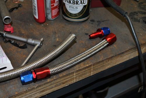 Here you can see the underpressure gauge in place, the engine is hooked up and as soon as I have time to finish the rev counter optical probe it is ready for its fifth and hopefully last test run. I want to start building the power turbine section now so please work perfectly this time! 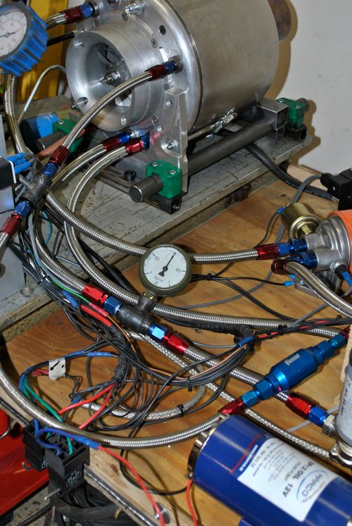 Cheers! /Anders |
|
|
|
Post by pitciblackscotland on May 18, 2012 16:50:49 GMT -5
Hi Anders, It will be interesting to see how the NordLock washers hold up for your next test run, fingers cross Cheers, Mark.. |
|
|
|
Post by racket on May 18, 2012 19:11:01 GMT -5
Hi Anders
Fine looking engine :-)
Cheers
John
|
|
ashpowers
Veteran Member
Joined: February 2011
Posts: 207
|
Post by ashpowers on May 18, 2012 21:49:06 GMT -5
Hi Anders,
Looking very nice!
On the ngv/turbine baseplate there appear to be two holes, 180-degrees apart, possibly 3mm diameter, just around the periphery of the shaft/bushing bore. Are those cooling air holes or?
Look forward to hearing about your next test run!
-Ash
|
|
|
|
Post by Johansson on May 18, 2012 23:11:35 GMT -5
Thanks guys!
The Nordlock washers should do its work, they are at a relatively cool place being that close to the bearing house and within the cushion of cooling air behind the turbine wheel.
You are correct Ash that the two holes is for cooling the turbine hub, courtesy of John who suggested that some bleed air in that area would keep heat away from the turbine shaft.
Cheers!
/Anders
|
|


