|
|
Post by madpatty on Jun 13, 2014 10:58:13 GMT -5
Hi everyone,
Couple of days ago this idea originated of building a jet engine with an Annular Combustion Chamber of design same as 10/98 and TV94 engines already built by cool experts here...
So finally started it today after acquiring some basic details from Johansson and John rearding the same....
This project will be a small one as compared to TV94 engine and will be solely based on the parts readily available near me...
Moreover this is my first project and i havent got any experience of high tech CNC milling etc.(wtf manual milling is costly here)
Engine will be build around Holset HX35 turbine and compressor with the use of standard components and journal bearings...
Few details on the turbine and compressor are as follows:-
COMPRESSOR
inducer- 54 mm
Exducer-83 mm
Tip height- 4.90mm
TURBINE
inducer- 70 mm
Exducer- 58mm
Shaft overall length- 173.5mm
Moreover i will try to fastrack the project and updates...
|
|
|
|
Post by Johansson on Jun 13, 2014 11:54:23 GMT -5
Great to have a new interesting build thread here!
The turbine exducer might be a tad small though with only 7% larger area than the comp inducer.
|
|
|
|
Post by madpatty on Jun 13, 2014 11:59:27 GMT -5
Hi Johansson,
Finally got the guts to start building with such a little experience of such an engine....
Don't think if anything could be done of the small turbine...
Still suggestions are welcome....
Cheers.
|
|
|
|
Post by Johansson on Jun 13, 2014 12:10:58 GMT -5
Do you have the HX35 already, or can you reconsider and try to find a more suitable turbo?
|
|
|
|
Post by madpatty on Jun 13, 2014 12:18:28 GMT -5
More or less its with me...
Or i should say its the largest one readily available with all internal components so thats why i have decided to use it....
|
|
|
|
Post by madpatty on Jun 13, 2014 20:36:39 GMT -5
Today i did a rough drawing of the proposed compressor diffuser.... Diffuser angle 20 degrees... 15 wedges... Diffuser start diameter 88mm (compressor exducer was 83mm) I read it somewhere here that a compromise ratio for vaneless space to be kept is 1.06 (d2/d1 in drawing) Diffuser to elbow in chamber 134mm Total OD 162 mm... 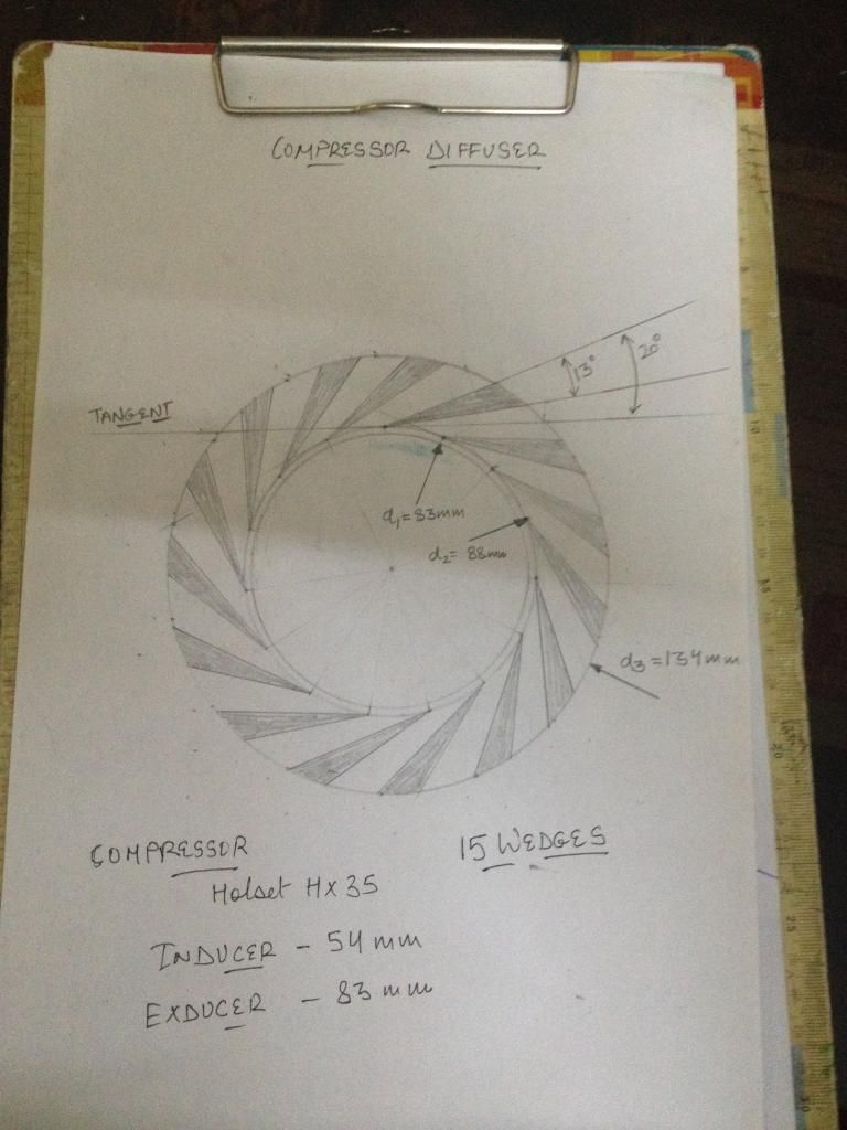 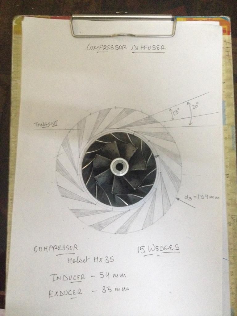 Cheers. |
|
|
|
Post by madpatty on Jun 14, 2014 8:20:20 GMT -5
Today i fabricated the diffuser plate for internal components... Wedges are yet to be milled... 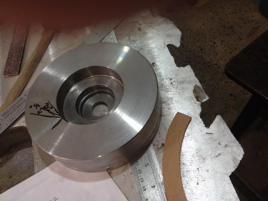 All the components(thrust plate, oil slinger etc) will be placed in these grooves... The shaft tunnel will contain both jouranl bearings and a thrust collar... Cheers. |
|
|
|
Post by madpatty on Jun 14, 2014 13:14:20 GMT -5
Casting the diffuser plate can also be one of the options... This will reduce the amount of machining that will need to be finally done.. Prepared the wooden pattern ready for the casting process... 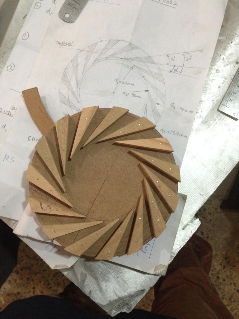 Removing the material for axial portion of the diffuser... 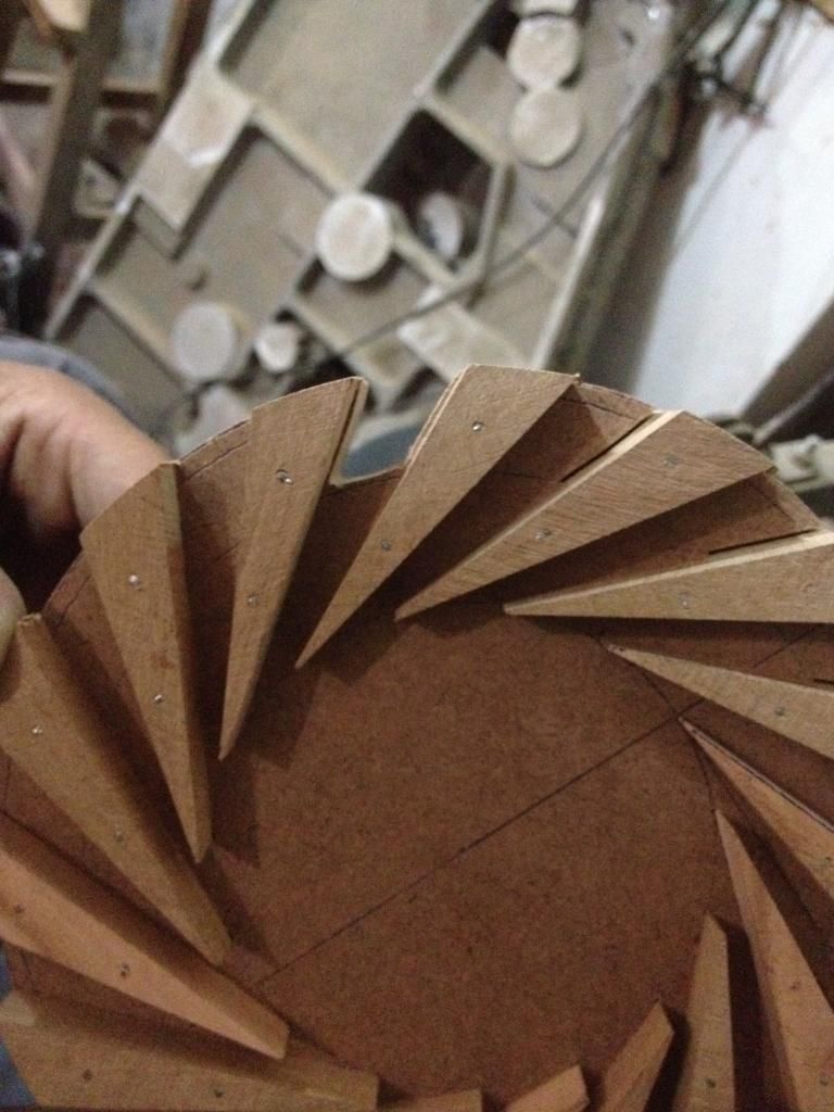 And The Final piece 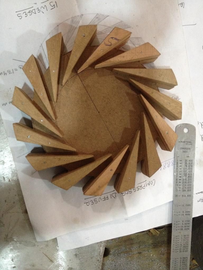 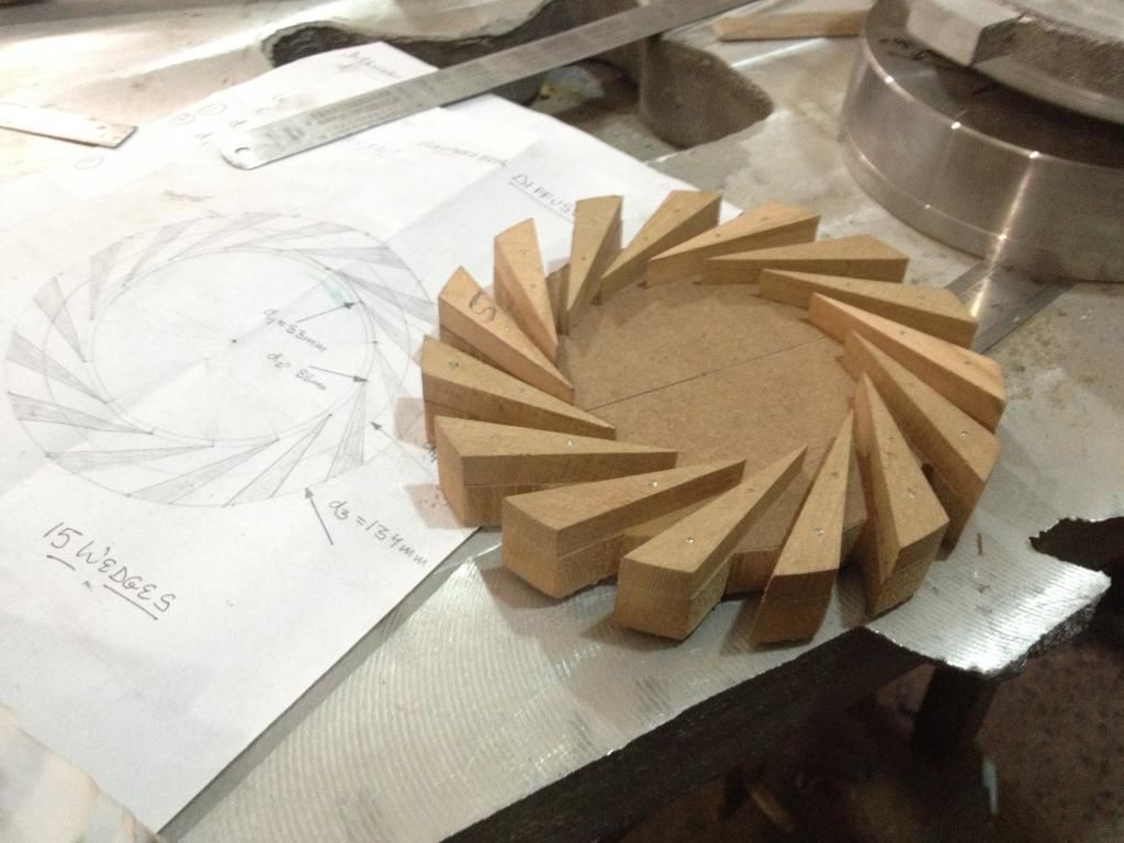 Cheers. |
|
|
|
Post by madpatty on Jun 15, 2014 1:24:50 GMT -5
So for the time the diffuser will take to complete i am thinking of starting the work on Turbine Plate...
After conversation with Racket i came to know that there are many variables to determine before choosing the NGV angle and number of vanes...
CAN anybody brief a bit on what all i need to do before starting the NGV section...
How could i calculate those variables...any tips?
Thanks,
Patty
|
|
|
|
Post by madpatty on Jun 15, 2014 22:52:29 GMT -5
Hi guys,
Needed to decide what is the design mass flow of the engine and the throat area neede for the turbine NGV....
Can anybody help me out calculating those or just describe the method..?
Any tips are welcome..
Thanks,
Madpatty
|
|
|
|
Post by racket on Jun 16, 2014 1:51:21 GMT -5
Use a figure of ~11 lbs/minute/square inch of inducer area, so for your 54mm inducer , thats ~40 lbs/minute or 0.65 lbs/sec .
Whether you'll have that mass flow depends on the throat area of your comp diffuser , you'll need to do the design calcs for it , they're in the Kamps book, .... which you should have read and reread at least 3 or 4 times before starting this project.
Cheers
John
|
|
|
|
Post by madpatty on Jun 16, 2014 1:58:13 GMT -5
Thanks John,
I will get back to you with the exact number...
Cheer,
Patty
|
|
|
|
Post by madpatty on Jun 16, 2014 7:24:26 GMT -5
Castings arrived today... Though the surface was very grainy and rough but there are enough clearances already to machine the part for the exact dimensions and finish... 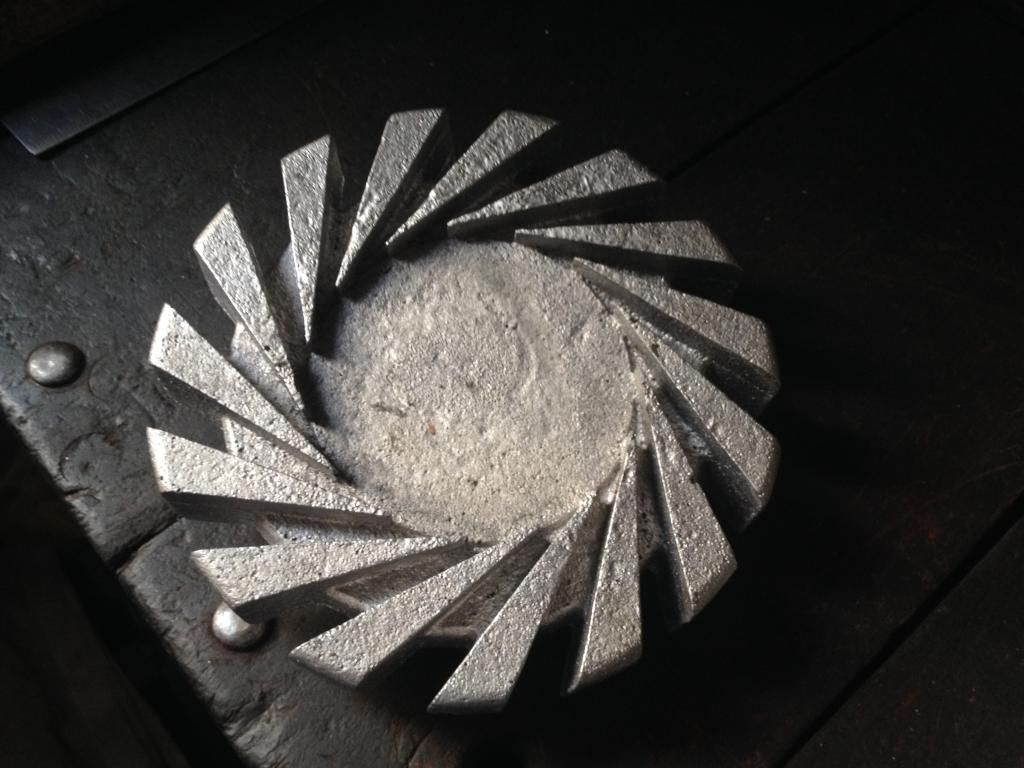 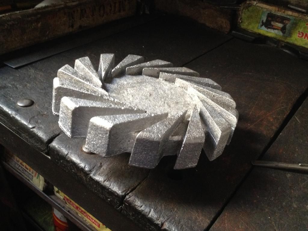 Cheers, Patty |
|
miuge
Veteran Member

Joined: March 2014
Posts: 199 
|
Post by miuge on Jun 16, 2014 11:53:45 GMT -5
Sorry to say, but that casting looks terrible?! I think you could have done it better and faster from solid, that one needs a lot of grinding..  Are you sure that only the surface is bad quality? |
|
|
|
Post by madpatty on Jun 16, 2014 12:06:47 GMT -5
Hi Miuge,
It was discouraging...LoL
I know its very rough but i had already kept everything on the plus side so that i can grind it afterwards...
Moreover you wont imagine how milling was to cost me a good fortune so in order to fit it in a budget i had to do that...
All the surfaces are to machined...
Thanks Miuge.
MOREOVER any tips from anybody are most welcome.
|
|


 Are you sure that only the surface is bad quality?