|
|
Post by madpatty on Jun 24, 2014 15:22:49 GMT -5
Hi Racket,
Today i rechecked all my calculations starting from the diffuser till the NGV section throat area...you mind if you can have a look at them and tell me if they are towards the correct side??
1.Assuming the mass flow of 40lbs/min(0.30kg/sec) at 3.0 pressure ratio and 75% efficiency....(ambient 30 degree celsius taken)
2. density of air at compressor outlet comes out to be 1.6477kg/m3 at 98 degree celsius.
3. outflow angle becomes 17 degree.
3. Assuming negligible density changes between the compressor outlet and diffuser inlet:-
radial area at diffuser inlet becomes equal to radial area of compressor outlet(i.e 1320 mm2)
therefore throat area = radial area * sin(17degree)
4. Throat area comes out to be 1320 * sin(17) = 385 mm2
5. Throat width in my case is 5 mm and wedge axial length is 5 mm. Total 15 wedges and this corresponds to throat area of 375 mm2.
Was tHE ABOVE STEP CORRECT ??
After performing detailed calculation regarding the NGV section:-
1. assuming NGV inlet temperature of 650 degree celsius and reaction level of 0.5.
2. Gas density at turbine 0.715 kg/m3 and at outlet 0.47 kg/m3.
CALculating the NGV's area now:-
It comes out to be 860 mm2(0.00086m2)
NOW is this the NGV throat area or we have to again use some (*sine(angle)) to get the throat area as we did in the diffuser case.??
Thanks,
Patty
|
|
|
|
Post by racket on Jun 24, 2014 18:54:24 GMT -5
Hi Patty
Yep , diffuser throats at 5mm X 5mm X 15 of , theoretically , ...........probably add a tad more on for boundary layer , maybe 5.5mm throats better .
NGV throat area is about right , it'll depend on just how efficient the nozzling is, as to the actual area , it looks like you used a slightly lower efficiency to me , but go for your 860 mm2
Cheers
John
|
|
|
|
Post by madpatty on Jun 24, 2014 21:35:15 GMT -5
An update on the progress so far... Had the shaft tunnel completed along with the Stainless steel plate to which NGV blades will be welded....(calculations had been done).... 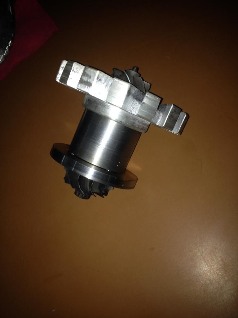 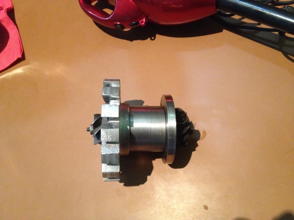 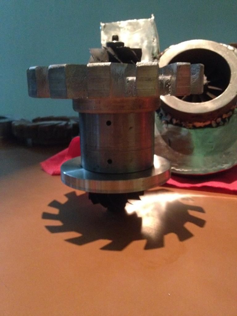 Will complete that NGV work today and post the pics... Cheers, Patty |
|
beaker
Member

Joined: March 2014
Posts: 18 
|
Post by beaker on Jun 25, 2014 6:01:22 GMT -5
Great work Patty, if you keep going the way you are your motor will be running in no time.
I gota pull my finger out and get mine finished.
Will be great to see yours running
Keep up the good work!
|
|
|
|
Post by madpatty on Jun 26, 2014 12:16:55 GMT -5
Hi,
A very basic question was originating inside my mind for quite some days now as soon as i started designing the diffuser for my engine...
Will there be any advantage/disadvantage of using longer radial length of the wedges for the diffuser(keeping the throat area same).....i.e. increasing the overall diameter of the engine including the diameter of the flametube...??
Just wanted to be on the safer side if there is any advantage like better air flow inside engine etc.
Thanks,
Patty
|
|
|
|
Post by racket on Jun 26, 2014 17:21:07 GMT -5
Hi Patty
It a case of compromises, as with most things with our engines , a bit larger diameter shouldn't be a problem and would most likely improve the diffusion process leaving the turning to axial flow until the air has slowed appreciably , but , too long of diffuser vanes can increase the frictional losses .
A slightly larger outer casing will allow more room for a larger flametube cross section as well as a wider flow passageway for the air around the flametube to help lower losses .
The main thing is to not be too small, a bit too small and you can have problems that can't be easily fixed or even unfixable resulting in an engine that won't work , but too large will only reduce efficiency a bit but the engine will/should work.
My FM-1 engine had a 12 inch casing , the 9/94 had a 9 inch casing and the 10/98 had a 10 inch casing , all with roughly the same mass flow, actually the larger FM-1 engine had ~10% less flow due to a ~5mm smaller inducer diameter than the TV94 comps .
Cheers
John
|
|
|
|
Post by madpatty on Jun 26, 2014 21:24:47 GMT -5
Thanks Racket,
I will try to keep the diffuser and outer casing at an optimum level..
Hopefully it helps!
Cheers,
Patty
|
|
|
|
Post by madpatty on Jun 26, 2014 22:04:24 GMT -5
Hi Racket,
I am facing the difficulty of how to lubricate the thrust bearing....
In my case it is half moon like structure....
I am not getting how to supply it the pressurised oil and how to arrange the drainagle of the oil....?
Thanks,
Patty
|
|
|
|
Post by racket on Jun 26, 2014 23:04:48 GMT -5
Hi Patty
LOL......You're the designer , just design in some lube passageways to and from the thrust bearing :-)
Do a Google search for "turbocharger lubrication" images to find a solution .
Cheers
John
|
|
|
|
Post by madpatty on Jun 27, 2014 3:38:09 GMT -5
Hi Racket,
What thickness NGV are enough to endure the heat in the engine....?
Thanks,
Patty
|
|
|
|
Post by racket on Jun 27, 2014 4:23:32 GMT -5
Hi Patty
1.5mm
Cheers
John
|
|
|
|
Post by madpatty on Jun 27, 2014 8:39:26 GMT -5
Progress update: Work on the NGV's almost done.... Very tiring working with stainless and above that when you dont have right tools for the job... 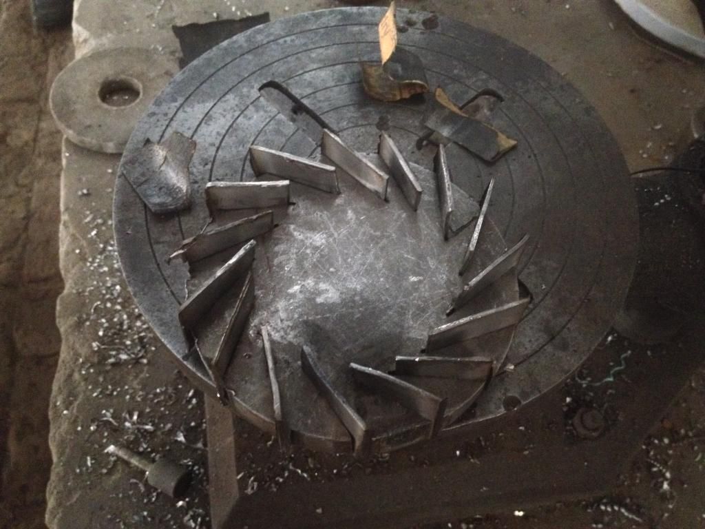 Will be fabricating the plate for the evaporator tubes tomorrow... ANy suggestions on the number and diameter of EVAP tubes are welcome... Cheers, Patty |
|
|
|
Post by racket on Jun 27, 2014 18:01:14 GMT -5
Hi Patty
Follow the advice in the Kamps book .
As a rough guide, the total "internal" flow area of the evaporators need to be ~10% of the inducer area , and the total surface area of the evaporators, about 6 times inducer area , you need sufficient number of evaporators to provide adequate coverage of the flametube crossection
Cheers
John
|
|
|
|
Post by madpatty on Jun 28, 2014 8:44:02 GMT -5
Hi Racket,
How much does the clearance between tips of NGV and Turbine inducer tips matter....?
Is there anything to be taken care of in it
My turbine inducer is 70 mm and what it NGV is kept at say 80mm diameter?
Thanks,
Patty
|
|
|
|
Post by racket on Jun 28, 2014 17:35:08 GMT -5
Hi Patty
Sounds OK at 80mm dia .
Cheers
John
|
|


