|
|
Post by Johansson on Dec 20, 2014 16:07:52 GMT -5
Very interesting posts Chris, thank you very much for writing this up!
|
|
|
|
Post by finiteparts on Dec 22, 2014 0:34:10 GMT -5
Just thought that everyone might enjoy seeing some pictures of this NGV out of a larger aircraft engine. I have been unable to identify it and the cooling insert and caps have been removed, which would have likely had the p/n on them. But it is fun to realize that this part operates in an environment that is hundreds of degrees above the metals melting point. This one shows some nice distress due to the loss of the thermal barrier coating (TBC)...all the TBC has been removed for inspection purposes, but you can see the spot that came off in operation. You can see how the hot spot at the location with the TBC loss caused excessive mechanical stresses that unzipped the local cooling holes. Also note the nice cobalt blue color due to the cobalt diffusion and the subsequent cobalt oxide formation. I have a ton of different nozzles that I have bought just to enjoy looking at the thermal and mechanical distresses that occur up close. 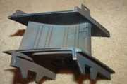 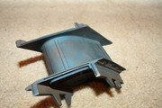 The chord length is roughly 4 inches and the height of just the vane is 2.5 inches. 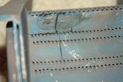 There is a lot of the engine airflow budget spent on keeping these parts alive! Look at all these "gill" holes.... 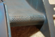 Another thing that you will notice about this more "modern" NGV, is that the leading edge is quite thick and blunt....this helps it to be less sensitive to off incident entrance flows. Enjoy! Chris |
|
|
|
Post by finiteparts on Dec 22, 2014 1:13:51 GMT -5
I was chatting with some one on the design of the compressor diffuser section and I thought that it would be good to share some links. The first is an often cited reference on straight channel diffusers (especially for centrifugal compressors) by Peter Rundstadler Jr of the Creare Corp...yep, the same ones from the previous post that did all that work on high pressure centrifugal compressors...thus the need for high mach number diffuser maps. www.dtic.mil/get-tr-doc/pdf?AD=AD0865300Starting around page 140, you can see some diffuser maps to help you get a good estimate of pressure recovery that you can expect from your straight channel diffuser. Trying to design them just by using the conservation of mass equation is not going to work for such a highly compressible flow...so these maps are invaluable tools to estimating you diffuser performance potential. The second link is just an online version of Hill and Peterson's text, in case you are just using Thomas Kamps book and need a more involved text, but are strapped for cash. This one is a good reference, but it is just ok for our purposes...it doesn't cover radial turbines and the figures sometimes leave something to be desired...but it should help. Sorry...the link to Hill and Peterson's book has been deleted due to the original page being removed from the university's website...
Kamp's book is marginal for the simple stuff...you will quickly discover that you need more. I hope this helps! Chris |
|
|
|
Post by finiteparts on Dec 22, 2014 1:49:48 GMT -5
I recently read a paper by some folks at Queen's College in Belfast, titled, "Numerical and experimental study of the performance effects of varying vaneless space and vane solidity in radial inflow turbine stators" , ASME GT2008-50261
It was a well done paper and the research seemed pretty relevant to what we are doing. Boiling down the paper to the highlights for what we might use in our designs...
1. The vaneless space between the vane trailing edge (TE) and the rotor inlet (r_le), defined as a ratio, R_te/r_le, needs to be a balance between:
a. Too long, there are increased frictional losses due to the longer flowpath
b. Too short, wake and jets from the NGVs do not mix out causing increased non-uniformity at turbine inlet
c. this is not surprising...see the same sort of thing in reverse for centrifugal compressors
d. Flow non-uniformity at turbine inlet drives turbine flow losses, blade vibrations and can lead to fatigue of blade tips
2. Best efficiency was at R_te/r_le = 1.13 ~ 1.175, but flow uniformity was still not good
3. Uniformity was improved up to around R_te/r_le = 1.25 then not much change, for only a 1/2% efficiency hit.
4. Increased blade count reduces blade loading (better flow control) and leads to more uniform flow at the turbine inlet.
5. Blade solidity (NGV chord (c) divided by the space between the trailing edges (s)), c/s = 1.24 is optimal.
- can change increase or decrease vane throat areas by changing number of vanes, moving the trailing edge pitch diameter or vane thickness.
Good stuff.
~ Chris
|
|
|
|
Post by finiteparts on Dec 22, 2014 12:56:44 GMT -5
Here is a sketch to show what I am referring to above...hopefully this makes it more clear.... 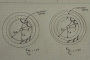 |
|
|
|
Post by finiteparts on Dec 22, 2014 13:58:56 GMT -5
Another interesting paper that I got my hands on was by Daimler AG, University Stuttgart and Imperial College London and it discusses some nice info on variable geometry turbines. The paper, "The Variable Outlet Turbine Concept for Turbochargers", ASME Journal of Turbomachinery, Dec 2014, Vol 136. They discuss their sliding sleeve concept for variable goemetry and it is pretty interesting how they justify the design, but the interesting thing to me was the information they had on variable vanes and the impact it has on the turbine reaction level. Since I respect copyrights, I redrew the basic concepts so that I could share the idea without stealing their work...if you want to see the better version, get your hands on a copy of the paper. This plot shows the effect of changing the degree of reaction for a given pressure ratio. 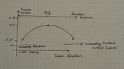 I forgot to label the y-axis, which is the overall turbine efficiency (which is a combination of the turbine and mechanical inefficiencies). So there was a previous question by Patty about driving the turbine with more impulse and from this data plot you can see that the efficiency falls precipitously when we deviate from the 50% reaction because of the high inlet losses that I was trying to explain in previous posts. If for some reason you wanted to go towards the higher reaction side, you experience higher exit losses. It might not be clear, but on the original plot, the efficiency is sort of flat till about 65% reaction, then it falls fast as you continue to increase the reaction. The plot of the inlet vectors is shown to help visualize how the flow angles change, 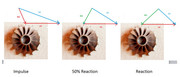 With some thought, you can see how the vectors for a fixed nozzle section might change as the mass flow is changed away from the design point. Just for a refreshers, C2 is the absolute discharge velocity, U2 is the tangential tip velocity and W2 is the relative flow velocity. The goal of the NGVs is to produce the absolute velocity C2, such that if you were riding on the turbine, you would see the flow approaching you at the relative flow velocity, W2. Another good point of reference, since they are dealing with turbocharger rotors very similar scale to ours, is that they mention the optimal relative inlet flow angle for this turbine is around -20 degrees, which is right around what I had been using in my calculations. - Chris |
|
|
|
Post by finiteparts on Dec 23, 2014 16:26:35 GMT -5
So I was talking with Patty and we were trying to derive a simple approach to predicting the choke flow through the inducer, so that you could estimate the sizing for the diffuser. The approach that is given in a few papers is to set the diffuser throat choke point to the choking in the impeller. The trick is that the impeller choke is based on a relative gas flow condition, so it is changing with rpm. I made a few attempts to derive this equation, then remembered that it had been derived in Dixon's book. So I popped this equation into an Matlab M-file and wrote this up in Word, since I was trying to capture this in another document for other purposes. So here it is...(by the way, the rpm at the bottom are in 10^5, but it looks like 10^6 because it is so small) (the write up and equations have been deleted from here and moved to the next post because they were too small to see). 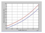 They also worked through a way to get the diffuser inlet flow condition based on the impeller outlet, which I will work through and post later. I knew the mass flow capacity of the impeller changed due to the change in the relative flow properties, but I have to say that the behavior is a bit different than I thought and to get such a clean solution is a very nice tool to have in the equation toolbox. Remember that due to the nature of the flow in the compressor, the inducer is usually the choke point, so if you measure out the dimensions of the choke plane in the inducer and then calculate the throat area, you can then predict from this the choke flow at the design point. By the way, the results seem to be pretty close. I picked a Borg Warner S475 compressor wheel, which on the map appears to choke at around 2 lbm/s at 96krpms. Roughed up a calculated throat area and what you see is the blue line. It may be a bit off, but it is pretty close for our predicting purposes. Enjoy! Chris |
|
|
|
Post by finiteparts on Dec 23, 2014 16:49:10 GMT -5
I tried to upload this on the last post, but it was way to small to read...so hopefully here, it is better sized. 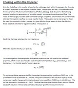 Enjoy! Chris |
|
|
|
Post by racket on Dec 23, 2014 19:32:14 GMT -5
Hi Chris
LOL.......you've got me baffled :-(
The "problem" with automotive turbos vs aircraft type comp wheels is the design requirements , autos require wide maps with "acceptable" efficiencies whereas gas turbines can have skinny maps as long as the efficiency is high .
Similar comp wheels on turbos can have varying flows and peak pressures depending on the compressor Trim as well as the housing A/R , ............its a hard job predicting flows just from wheel sizes.
Ideally we want high efficiency compression for our engines , this then dictates we "reduce" flow below inlet choking conditions.
Having looked at a fair few comp maps over the years I've come to the conclusion if we design for an efficient flow of ~11-12 lbs/square inch of inducer/minute we won't be far off if we run our comp to "safe" tip speeds ~1,500 ft/sec , but with the ready availability of billet compressor wheels with more modern designs and high potential tip speeds and pressure ratios that ratio can go out to > 15 lbs/sq in/min as is the case with the Garrett GTX5533R 49.5 Trim ( 93.8mm inducer) at tip speeds of >1900 ft/sec, the similar GTX5533R (same 133mm exducer) but at a 47 Trim ( 91.2mm inducer ) has a 14.3 lbs/sq in/min flow rate ..............max pressure ratio for the larger Trim is ~4.7 whereas the smaller Trim goes out to 5:1 at the same tip speed . .............efficiency at that max is a tad better with the lower Trim wheel , this will then have an effect on densities exiting the wheel and going to the diffuser , in the case of the larger Trim wheel it has a 0.81 A/R housing whilst the smaller Trim only has a 0.69 A/R there only being an ~11% difference in flows at best efficiency at same max tip speed .
There ain't no simple approach to predicting flows from IC engine turbo comps, too many variable built in by the manufacturers :-(
Cheers
John
|
|
|
|
Post by finiteparts on Dec 28, 2014 14:51:17 GMT -5
Hi John,
I think you are talking about trying to "guess" from historic data some sort of compressor flow capacity away from choke, while I am trying to show a method to estimate the choking conditions for the impeller. I am trying to provide a method to define the choke boundary...not where to select a design point...hopefully that clears things up.
It is important to know the swallowing capacity of the impeller in order to properly size the throat area of the diffuser. So providing the method to calculate the choke area of the impeller is the first step. Knowing how the area changes as the compressor speed changes is fundamental to understanding the systems dynamic behavior and the equation provided by Dixon and Hall is a nice tool to have for this. For some reason, I was expecting a more linear response, so "seeing" the non-linear response was very interesting, especially at the base concept equation level.
Without this bit of knowledge, it would be hard to determine if your compressor system is choke-limited due to the inducer throat or the diffuser throat. So, if the diffuser throat area is incorrectly sized, it would be hard to decide how to correct things. By design, a fixed diffuser will only be matched at one condition. Moving away from the design condition, the level of mismatch will change and losses due to off-incidence entry flow or excessive shear losses may shoot up.
I agree that looking at lots of maps is a great way to collect historic data and get a feel for how things behave, but since those maps are almost exclusively for vaneless diffusers, how are you going to use that information to drive a vaned diffuser design?
When you start talking about pressure ratios over 4:1, you are venturing into the realm of compressor inducer and discharge velocities approaching or exceeding the local sonic velocity and all the associated problems with such flow velocities...you, more than most of the engine builders on here, will need to know how/when the inducer chokes.
I guess the term "simple" was a bad selection...there are a lot of things involved, but starting with the basic turbomachinery equations and working through them builds the basic operational understanding that can be modified from research data to get very good map conditions.
~ Chris
|
|
|
|
Post by racket on Dec 28, 2014 19:28:32 GMT -5
Hi Chris There was an interesting article in the "Jet International" magazine of Sept 1996, that I kept, regarding choked flow and a method of comparing RC engines, it gave a maximum flow of 0.46 lbs/sec/sq inch of compressor wheel inlet area with inlet velocity of Mach 1.0 , but as most RC aircraft would normally only see a max inlet velocity of ~M 0.5 that flow would come back to ~0.34 lbs/sec/sq in (20 lbs/min/sq in ) , the article used "Q" for mass flow with M 1.0 at 0.3966 and 0.296 at M 0.5 , the article was written by a couple of retired RR gas turbine engineers, so I guess they have some idea what goes on . Unfortunately I feel they're still using full sized aircraft engine "thinking" where theres ram pressure and high "vehicle" speeds involved , for our land based engines using turbo based comp wheels I feel we need to modify our thinking . Even at 500 ft/sec inlet air velocity we've lost ~2psi of static pressure , and it gets much worse as the inlet velocity increases . As for inducer choking on our comps , some of the newer wheels must be overcoming that to a degree as the mass flow increases don't "suddenly" stop once relative inlet velocities go "sonic" , take the GT5533R with the 49.5 Trim I mentioned in my last Email , that inducer tip at 84,000 rpm is doing ~1356 ft/sec , with say ~550 ft/sec inlet velocity , the relative velocity is ~1450 ft/sec or ~M 1.3 , to have that inducer tip operating at < M 1.0 we'd need to be running at ~63,000 rpm with a PR of only ~2.9 :1 and flow rates of ~12 lbs/min /sq in of inlet area , not the 15.3 lbs/min/sq in at "supersonic" inlet conditions . The comp housing scroll A/R is a form of "diffuser throat" area , and will "control" flow rates to some degree , as is the case with turbine scroll A/R sizing where theres a single throat rather than multiple ones with a NGV stator .. Most turbo comp maps stop at the 60% effic island at flows still below "choked" flows, the comp is still capable of swallowing more air , its just that its not worth going there as the PR is poor for the energy being expended. If you'd like to go through my "thoughts" for my 12/118 engines comp wheel I'd be only to happy to try and convey them  Cheers John |
|
|
|
Post by finiteparts on Dec 29, 2014 13:49:26 GMT -5
Hi John, The mass flow rate per unit area (flow density) is commonly used in compressible flow calculations for sizing nozzle flows (such as ASME calibrated "sonics"...gas mass flow measuring devices). If you look in Saad's "Compressible Fluid Flow" (the one I provided a link to in a previous post) in Section 3.4, there is a section on the derivation and such. I hadn't thought about using that approach to approximate the maximum flow density at the compressor inlet prior to your previous response....I will have to incorporate that into my calculation software. But the takeaway is that they were probably not basing it on anything other than basic compressible flow concepts that hold regardless of the application. As for the ram pressure, I am assuming that you are concerned that the reduced static pressure is causing a reduction of mass flow at the inducer? Remember that the compressor maps are typically based on "total to total" conditions and the total pressure at the compressor inlet plane doesn't change (ignoring pressure losses due to poor inlet design)...once you start doing work to the fluid, then the total conditions change. So if you are using the above flow density concept or historic turbocharger compressor maps to base your designs on, there should be no difference....all that is baked into the data on those maps. The entire inducer does not choke at once, so there is not a "sudden" limit to swallowing capacity...also, remember that the choke area changes as the rotational speed changes...think of it as the flow area presented per second...as the rpms increase, the same area is presented quicker, thus essentially the approaching flow is seeing an increased flow area with which to pass through. The relative velocity at the tip may be sonic or higher, but the relative velocity at the hub is still very subsonic...one-dimensional approximations based on the tip conditions are not to be applied to the entire inlet...if you are trying to approximate the entire inlet, a RMS radius is often used. The 84k rpm speed line is dropping fast because more of the blade span is becoming unable to swallow more flow. As you go to the right on the speed line, the slope is getting nearly vertical at the 60% isoline. There might be a touch more mass flow capacity, but for Garrett's purposes, they are calling it choked...it could also be that the limited amount of data points taken does not allow them to accurately draw the slope of the speed line and they approximate choke in a similar manner to the equation I provided. If you go to Garrett's catalog, they define their "choke-line" as below their 58% efficiency isoline.  The fact that Garrett truncates their data on the compressor maps does sometimes make it harder to determine where the actual choke flow condition occurs...also they don't do a good job identifying to what conditions the data has been corrected to. Holset corrects most of their maps to 85F and 14.425 psi...while Borg Warner does most of theirs to 85.5 F and 14.706 psi. The Borg Warner EFR maps draw the speed lines all the way out to choke and are quite nice. 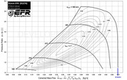 The vertical speed line is the indicator of choked flow somewhere in the compressor system...reducing the backpressure on the compressor does not allow any increase in mass flow for that fixed rpm....thus choked flow. The only way to increase the mass flow is to increase the rpm. The vaneless diffuser does not provide a "throat" as it is always has a larger area than the impeller discharge. Even the pinch region is usually selected to hold the discharge area constant for a time so as to stabilize the diffuser entry. I might not argue that it "controls" the flow rate, but I think a better description is that it defines a stable diffusion rate. I still don't see how it is going to help with a vaned diffuser. Additionally, if you don't use the ported compressor inlet that the map was based on, your surge line will be largely modified due only to the impeller, not even including the diffuser. 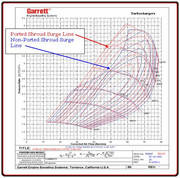 So you will need to be quite accurate with you diffuser vane setting such that you don't introduce regions of separation that would trigger surges and stalls. Now don't get me wrong, I think it is totally achievable to produce a good operating compressor system with this, but I just wanted to talk through the big design issues. - Chris |
|
|
|
Post by racket on Dec 29, 2014 16:13:52 GMT -5
Hi Chris
Yep ,comp maps can be confusing .
Somehow I feel this "conversation" is getting overly complicated and "theoretical" because choked flows are something we should never be approaching with our engines , either at low PR's or high PR's due to the poor compression efficiences , we need to be flowing along that high efficiency locus line and staying above the 70% point at max PR otherwise we simply use a lot of fuel flogging our air to death in the comp stage , theres little if any benefit to pushing our engines into efficiency flows <70% ...............I know the car guys always want to know how much air a certain sized turbo can flow, but for us its not so much what it can flow, but how well it can flow ...............to be honest, I've never ever thought about wanting to know the choked flow of any of my compressor wheels , its was irrelevant .
I've never said the vaneless space controls flow through any "throat" , the scroll A/R is matched to the wheels designed flow to "compliment/control" its flow, as for the reduction in axial height at the comp exit ( pinch) , it forces the air at a "higher" angle, maintaining/increasing radial velocity and in the process reducing the flow path, something I've incorporated into some of my designs to produce the desired vane leading edge angle and length of vane.
That Borg Warner map is for a very good compressor wheel, unlike a lot of wheels being used by engine builders .
LOL.............Yep , its possible to produce operating compressor stages , hopefully my 4th one will be as "successful??" as the previous 3 have been...........I just keep on using my trusty, circa 1958 Cohen and Rogers text
Would you have some thoughts on why theres big variations in the ratio of inlet area to outlet areas for various comps , some have a ~1.5 :1 ratio whereas others have a ~2:1 ratio irrespective of the blade outlet angles and potential pressure ratio capabilities.
Theres also that inducer tip angle, significant angular variations there as well , the more wheels I measure up the more confusing it becomes , I don't know whether its design differences or simply manufacturing requirements , there doesn't appear to be a logical thread :-(
An interesting Thread you've got going here :-)
Cheers
John
|
|
|
|
Post by finiteparts on Dec 31, 2014 15:04:22 GMT -5
Hi John, I guess the conversation could be a bit complicated for some out there, but I think these points are valid discussion material for those thinking about designing vaned or channel diffusers for higher pressure ratios. For vaneless diffusers you are right, you have no need to know where the choke boundaries are, other than basic curiosity. But the vaned or channel diffusers are a different situation. If you do your research on diffusers, you will see that they exhibit a peak pressure recovery as a function of their overall area ratio. Given the confines of the engine envelope, often you are stuck with a peak outlet area...so sometimes, you need to know how to set the throat of the diffuser to achieve a certain level of pressure recovery (especially if you are striving for high pressure ratios and/or high efficiency)...otherwise, you will just have to accept a lower level of pressure recovery than what is optimal and it's associated loss in efficiency. If you just "oversize" the diffuser throat, then you are likely getting low diffuser performance at the target design point. This is the main reason that designers switch from vaneless to vaned diffusers. The vaneless diffuser is simple, cheap and has the widest flow range at lower pressure ratios (at higher pressure ratios, this doesn't hold true)...but it does this at the cost of also having the lowest efficiency due to the long flow paths and potential for internal flow separation. As you put more stuff in the way of the impeller discharge flow, for example vanes or wedges, you increase the chances of flow separations that will limit your diffusers stability and thus range. Usually, you put this stuff in there to direct the flow (change the pressure field) and hopefully more efficiently recover the kinetic energy in the flow back into static pressure energy at the design point. So for all the readers out there, my suggestion is that if you want to design a engine for wide operation and ease of design, use a "low-solidity" vaned diffuser like what you would see in the old VT/ST-50 turbos. Solidity refers to the ratio of vane chord (C) to the pitch or spacing (s)... solidity = C/s See Figure 4 in the following paper...the (b) SVD diffuser would be consider a low solidity diffuser and the (a) VDA would be a high solidity (neglect the small pre-vanes shown). www.hindawi.com/journals/ijrm/2003/546204/abs/David Japiske, CEO of Concepts NREC and one of the experts in this field, suggests these rules of thumb for the low solidity airfoil (LSA) diffuser: Vaneless space between impeller discharge and diffuser leading edges, r3/r2 = 1.10 to 1.15 Radius ratio of the vane cascade leading edge to diffuser throat, r4/r3= 1.20 to 1.25 Radius ratio of the vane cascade leading edge to trailing edge, r5/r4 = 1.3 to 1.6 Inlet pinch ratio, b3/b2 = .85 to 1.0 Blading shape = NACA65(04)06 (0.4 Cl and 6% thickness) AOA = near 6.5 deg NACA rule Solidity = 0.8 to 1.0 His work has shown that LSA diffusers can have the same pressure recovery (Cp's up to 0.75) ability as a channel diffuser, but with a wider operable range up to pressure ratios in the 5's. So, the reason that I started looking into the choke boundaries is primarily due to the work of Micheal Casey (University of Stuttgart/PCA Engineers Limited) and Daniel Rusch (ABB Turbo Systems). They have put out some really good papers recently where they are essentially giving the engineers tools to predict compressor maps. The results are quite nice compared to the other map approximation methods from the past. The primary papers of interest are, "The Design Space Boundaries for High Flow Capacity Centrifugal Compressors", ASME Journal of Turbomachinery, May 2013, and "The Matching of a Vaned Diffuser with a Radial Compressor Impeller and Its Effect on the Stage Performance", ASME Journal of Turbomachinery, Dec. 2014. They follow the data from Colin Rodgers (consultant, formerly worked at Solar) ("Flow Range of 8.0:1 Pressure Ratio Centrifugal Compressors for Aviation Applications", ASME GT2005-68041) and H. Tamaki (IHI) ("The Experimental Study of Matching Between Centrifugal Compressor Impeller and Diffuser", ASME Journal of Turbomcahinery, Jan. 1999) and others, that for the widest flow range and maximum flow, the diffuser and impeller should choke at the same time. In their work, they develop the equations for impeller and diffuser choke flows, beginning with the equations derived in Dixon and Hall's book. Their previous paper ("The Design Space Boundaries...") developed calculations for the optimal inlet tip diameter and blade angles for a prescribed pressure ratio and flow. They extend that work to also provide the optimal diffuser throat area. As I work through this I may share it on here, but judging by your comments, I might just confuse people or make things overly complicated...so maybe not. Sorry, I took your prior statement, "The comp housing scroll A/R is a form of "diffuser throat" area , and will "control" flow rates to some degree , as is the case with turbine scroll A/R sizing where theres a single throat rather than multiple ones with a NGV stator .." as if you were saying that the diffuser does form a throat...I just wanted it to be clear to other readers that the vaneless diffuser does not form a throat and choking in a vaneless diffuser is not really possible, since the flow will always choke in the inducer first. You know, I bought a copy of Cohen and Rodgers 1951 text because of your good comments and although it is a good text, I actually like the newer version better. But that being said, I also have tons of other gas turbine design books because it is amazing how each author has his own take on things and there is a lot of insight that you can get from seeing many viewpoints. I was trying to determine which one was my "favorite", but they all have good and bad points, so I just can't decide. This post is getting long...I will continue on another one. ~ Chris |
|
|
|
Post by finiteparts on Dec 31, 2014 18:02:04 GMT -5
Ok...onto the variations in the impeller area ratio and inducer vane angles. The inlet to outlet area is one of the few knobs that the impeller designer has to play with for setting the discharge conditions and the internal diffusion ratio. We know that tips speeds are set by the required stage pressure ratio and we can play with the rotational speed and the discharge radius to achieve the required tip speed...but that rpm will then set the requirements for the inducer tip speed. So, let's assume that we have the tip speed set, we've picked a discharge radius and thus the rotational speed is set. We can reduce the discharge Mach number by sweeping the blade backwards, but since that also reduces the work put into the fluid, the rotational speed would have to be increased relative to a radially bladed impeller. Let's assume that this is already incorporated into the design speed....so now, the only knob we have to change the discharge conditions is the blade height (b). By increasing the height of the impeller discharge, we can decrease the radial discharge velocity vector, thus since the tip speed is fixed by the pressure ratio requirements, the absolute discharge velocity is also reduced. Reducing the discharge velocity unloads the diffuser requirements and thus usually correlates to increased stage efficiencies. There was some work done by NASA Lewis and the US Army on the effect of the area ratio. The pertinent paper is, "Effect of Area Ratio on the Performance of a 5.5:1 Pressure Ratio Centrifugal Compressor", L.F. Schumann, D.A. Clark and J.R. Wood, ASME Journal of Turbomachinery, Jan. 1987. On a hunch, I checked the NASA Technical Report Server and yep, there is a copy available online... ntrs.nasa.gov/archive/nasa/casi.ntrs.nasa.gov/19860009819.pdfIf you go to Figure 10, it shows quite well how the efficiency falls as the tip height is reduced...the reduced tip height means that the fixed clearance between the impeller and the casing is a larger percentage of the actual passage area. I thought that was pretty neat. You can also see how the impeller equivalent static pressure recovery coefficient (Cp IMP) falls as the normalized clearance (Cl/ b2) increases as more of the flow spills over the blades from the pressure to suction sides or more secondary flows come into play. They find for their impeller, that the most efficient area ratios are somewhere between 2.55 to 2.748. The plot in Figure 11, of the Cp IMP, shows a behavior typical to almost any diffuser, even though this is a compressor impeller...the pressure recovery rises till the diffuser experiences a flow separation and then the ability to recover the pressure falls off quickly. Thus due to the internal diffusion, you can think of the impeller behavior as a diffuser. The rate of diffusion through the impeller, like any other diffusion process, defines the stability of the system. Some use area ratio to define the parameters, others use what is termed a diffusion ratio. The diffusion ratio, DR is often calculated as, DR = W1s / W2 ( W1s = relative velocity at the impeller tip and W2 = relative discharge velocity of the impeller) There has been a ton of work trying to define "safe" operating limits, similar to other diffuser maps, but not with a lot of success. There is even disagreement on the best way to define the DR. Colin Rodgers has a paper that is often cited in other work, "Impeller Stalling as Influenced by Diffusion Limitations", ASME Journal of Fluids Engineering, March, 1977, that he did back when he worked at Solar. I have been meaning to go through that one and I will keep you posted when I do finally get around to reading it. A quick looks seems to indicate that he has a much more involved calculation of what he is terming a diffusion factor, DF...he shows a table of limiting diffusion ratios (W1 rms/ W2 ....so he is using the RMS value for the radius to determine the inlet conditions)...the values are between 1.6 to 2.4. The other thought that I had that might be effecting both the area ratios and the inducer tip angles could be that they are trimmed wheels. If the fundamental wheel for a given frame size is trimmed, the inducer angle would shift and the discharge passage height might be quite variable depending on how they set their rules for trimming. The vane inducer angles are set based on the relative flow properties, so I can only assume that they are set properly based on the inducer swallowing capacity. I know the range of inducer flows, the design point selection, the tip speed required at the design point and other things play into this, but for many newer applications, these vane settings have to cover a very wide operating space and thus they are probably a compromise around some middle operating condition. I know that Whitfield and Baines, in their "Design of Radial Turbomachinery" book, they derive some optimal blade angles. I will go back over that to see if anything stands out. I wonder if you need to be looking at another variable with which they would more accurately align, such as flow coefficient or work coefficient? Also, have you gone through the Centrifugal Compressor chapter in the Hill and Peterson book that I posted? They worked through some of the normalized design approach similar to what Whitfield and Baines did in their book, just to a smaller amount. Finally, here is a good papers on IHI's compressor design and how they approached the design issues of high pressure ratio... www.ihi.co.jp/var/ezwebin_site/storage/original/application/9e53d8849d72ff65891867ea69e338a8.pdfTheir is a really nice section on their approach to inducer design...plus the rest of the paper is interesting too. Enjoy! Chris |
|


