Feathers
Veteran Member
  
Joined: August 2010
Posts: 169
|
Post by Feathers on Dec 28, 2015 23:11:52 GMT -5
Hey everybody! The semester is over, and we've go time to spend at the machine shop over our winter break  Racket, I've looked into the RLV #35 chain we're using. It's pre-stretched, and according to the karting forums, has been run in 250 2-stroke shifter karts to 75-80 HP without problems. We'll definitely avoid a master link (one less piece to fly apart over a tiny sprocket  ) At Racket's suggestion, we've gone with the "rattly" 6006 bearings. They're much, much larger than necessary, but might be forgiving if we make a mistake (we will). Here's a cutaway of the power turbine section. Torque transmission to the shaft is via slotted interfaces with the sprocket, and with the turbine nut. We're confident that this will work in the case of the turbine, however the sprocket is of such a small diameter, that getting torque through the fixture might be tricky, while maintaining perfect alignment. We're open to suggestions. 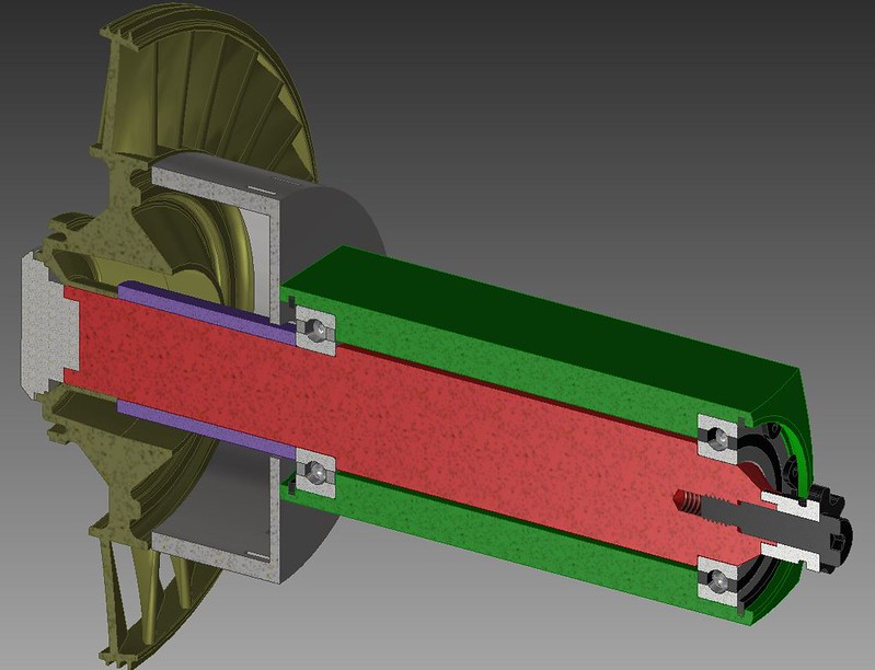 We just got to machining the main shaft. Its 304SS, a little softer than would be ideal, but it should be tough enough to handle whatever we throw at it. It's also over an inch in diameter. No bendy-bendy unless something freaky happens. 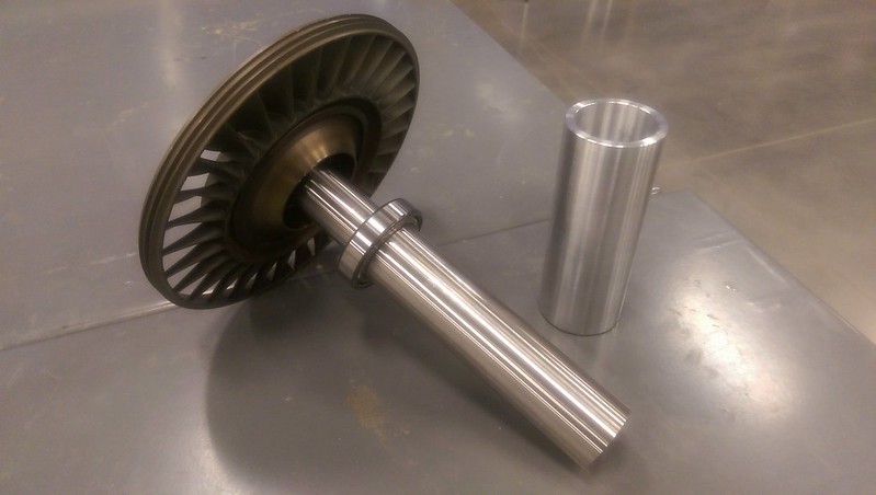 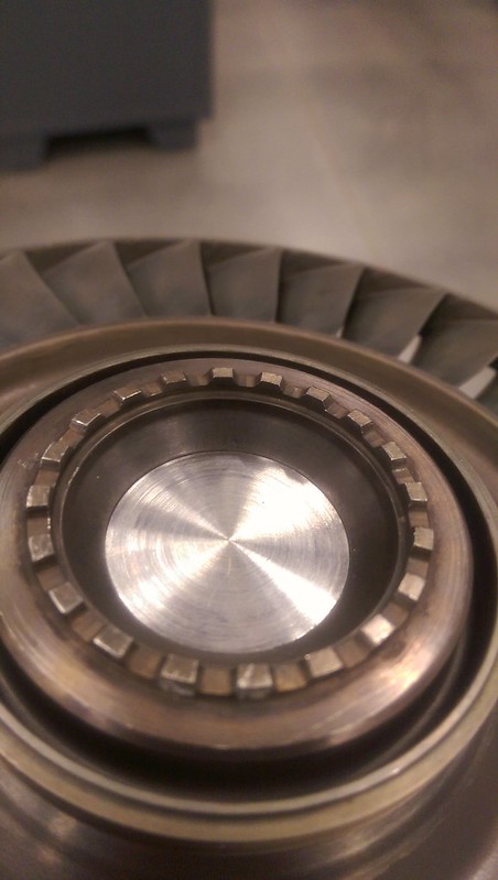 This is the first significant work I've done on a lathe, and I'm really enjoying the process of turning precision shafting and parts. Hopefully I don't muck this up too badly  We'll be headed in to finish up the work tomorrow, and start in on our shaft tunnel. Thanks for the help! |
|
|
|
Post by smithy1 on Dec 29, 2015 14:41:39 GMT -5
Nice work Feathers, that should work quite well, 304SS will be fine, not too soft, not too hard ....be sure to balance it as an assembly..!
Cheers,
Smithy.
|
|
|
|
Post by racket on Dec 29, 2015 18:26:09 GMT -5
Hi Feathers
There are karting sprockets that fit on a taper with keyway , thats the type I used on my 2 shaft kart , it produces an accurate alignment .
Do you intend to use sealed bearings??
You might need to provide some cooling air to the freepower hub area .
Cheers
John
|
|
|
|
Post by smithy1 on Dec 29, 2015 20:06:25 GMT -5
I see some slots in the hub shroud housing John....maybe they are for cooling?? I expect most of the "hub heat" will go into the shaft.
Cheers,
Smithy.
|
|
Feathers
Veteran Member
  
Joined: August 2010
Posts: 169
|
Post by Feathers on Dec 30, 2015 3:20:24 GMT -5
Racket, The turbine-side bearing is shielded (seals probably wouldn't like the heat), and the sprocket-side bearing is sealed. We'll be removing the shield and seal towards the inside of the bearing tunnel, so they're open to oil. This is illustrated in our newer drawings. As well, we're going to machine in a very simple oil galley, to deliver bleed oil directly to the bearing race. There will be a simple oil drain (not shown), and a bleed air feed (not shown). Both oil and bleed air will be metered. These galleys are illustrated in Blue, in the cutaway. Of course, we don't care what happens to oil that leaks past the turbine side bearing, but oil leaking past the sprocket side bearing is going to make a mess. Because of this, we're installing a shaft seal to keep things clean  A bit of bleed air to "coax" oil either back to the drain, or through the turbine-side bearing (hopefully a majority to the drain, to be returned to the reservoir) You can see the oil galley, shielded and sealed bearings, removed shields/seals, and shaft seal in the drawing below: 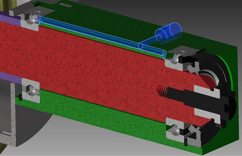 I think I've also come up with a solution to the problem of torque transmission to the sprocket... The redesign above involves machining the "bulk" of the sprocket to a precision insert fit to the shaft, which will keep it nice and concentric. Instead of a traditional keyway, I was thinking we could get away with a cylindrical key? That makes machining very simple. Here's another picture of the oil galley in the bearing tunnel: 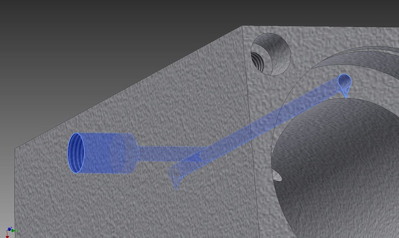 Smithy, The holes in the hub shroud housing will actually accept tangs that protrude from the leading edge of each nozzle guide vane. We would have these CADed, but we need to characterize our gas producer before we design the NGVs. Right now, it's just a place to put them when we get around to designing them.  Thanks for the input! We've also machined part of our starter motor engagement. This tube holds the motor so it is free to slide back and forth about half an inch. Slots accommodate screws that hold the rear of the motor together. It fits like a glove and slides very nicely. 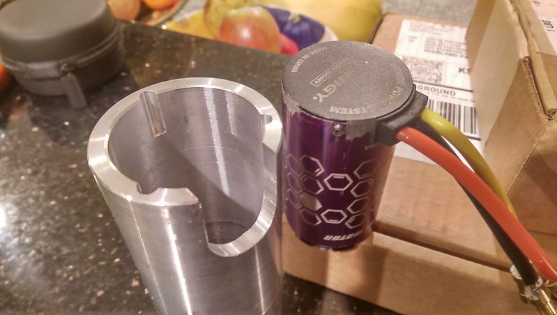  |
|
|
|
Post by racket on Dec 30, 2015 3:39:22 GMT -5
Hi Feathers
I'll try and find some drawings of the setup I used in the 2 shaft kart , will post tomorrow
Cheers
John
|
|
|
|
Post by racket on Dec 30, 2015 19:44:19 GMT -5
Hi Feathers
I've searched and searched but no drawing , bummer , so I'll have to try and explain things .
Firstly , your sprocket end seal might be a problem at 20,000 rpm , with a 30mm bore the rubbing surface will be doing >6,000 ft/min and could have extra pressure applied to it by any air/gas pressure loads from static pressure upstream of the turb wheel, and is the reason why I went with an "air seal" at that end , using bleed air fed into a plenum surrounding the shaft with some leakage "outwards" towards the sprocket through the minimal clearance between shaft and shaft tunnel endcap bore , whilst the majority of the bleed air went into the shaft tunnel thru a more generous clearance between shaft and endcap bore.
The air going into the shaft tunnel then encountered the total loss lube drip and carried it through both bearings and out into the turbine and was burnt , the combination of minimal lube and plenty of air keeps the bearings alive , ..........there have been large aircraft turbines that use total loss to the turbine bearing .
With your bearings , I'd "fix" the sprocket end bearing but have the turb end bearing free to slide in its recess for shaft expansion and to relieve it of any thrust carrying duties , better to have the cool end do all the work .
Cheers
John
|
|
Feathers
Veteran Member
  
Joined: August 2010
Posts: 169
|
Post by Feathers on Mar 7, 2016 13:53:06 GMT -5
Hi Racket, The idea for a shaft seal actually came from the DIY turboshaft minibike that Mikko and his racing team built. We can see how it works. It will be obvious if its a problem, and can be removed easily  . Thanks for the tip! We will run a shrink-fit on the cold side bearing, make sure it's nice and "on there". Plans have been to run a sump (of sorts) to the shaft tunnel, and supply plenty of air and oil, understanding that we will loose some. We'll see how this goes  Pictures of progress on the way! |
|
miuge
Veteran Member
  
Joined: March 2014
Posts: 200 
|
Post by miuge on Mar 8, 2016 9:39:29 GMT -5
Hi Feathers, Our shaft seal worked fine with no occurred leaks, I'd estimate it reached 20krpm while turning it rear wheel on the air. Our shaft is 20mm though so it has less surface speed. We're working on a new powerturbine axle too + few other upgrades on the bike  -Mikko |
|
Feathers
Veteran Member
  
Joined: August 2010
Posts: 169
|
Post by Feathers on Mar 8, 2016 12:03:05 GMT -5
Here's an update: We got a 3D printer! Its first job is printing upgrades for itself, including an entirely new X-carriage, cooling ducts, wire chain, spool holders, etc. We'll use this for, well, whatever we find we need that can be made of ABS  . 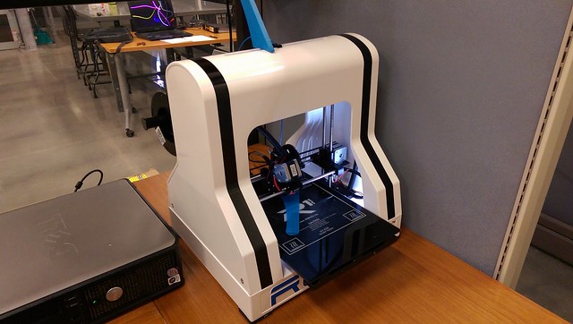 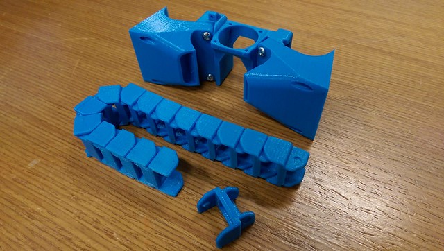 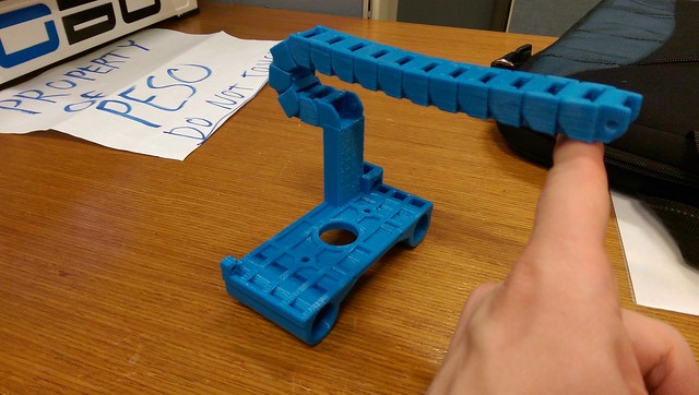 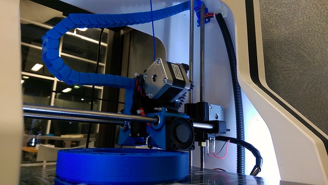 We also got our starter engagement system running! The FADEC board has arrived, has been populated, and all the microcontrollers are working well. 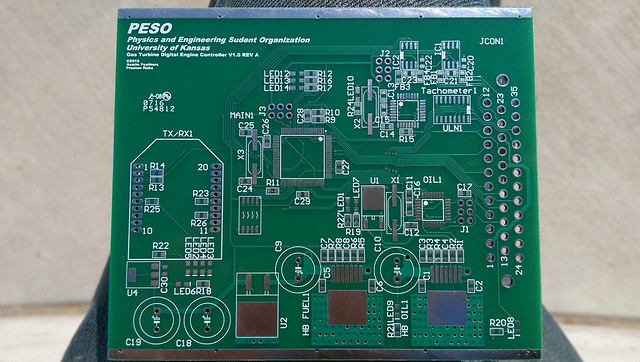 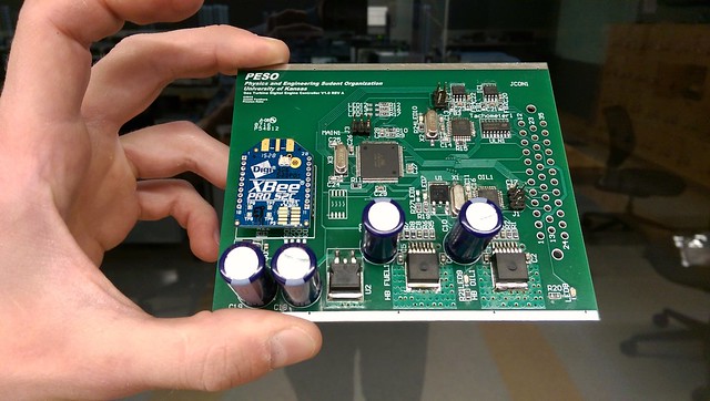 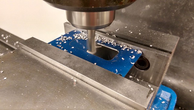  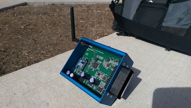 The kart frame has been painted, and it's starting to look like a more serious machine. 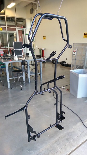 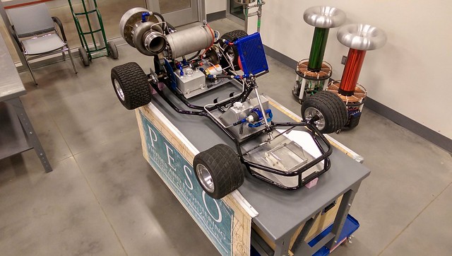 |
|
|
|
Post by Johansson on Mar 8, 2016 16:09:25 GMT -5
Very cool and serious looking project!
|
|
Deleted
Joined: January 1970
Posts: 0
|
Post by Deleted on Mar 8, 2016 17:54:52 GMT -5
Hi...... very impressive project, but do have a little concern around return oil line from the turbo. the reduction in diameter and restriction of flow in a 90 bend, don't see breather for the oil tank ?
|
|
Feathers
Veteran Member
  
Joined: August 2010
Posts: 169
|
Post by Feathers on Mar 29, 2016 10:10:17 GMT -5
Hi Andy,
The oil return line is 1/2" OD braided tubing, hopefully this is enough!
The oil tank will of course have a large filtered breather. This just hasn't been installed yet. We have a weld-in barb and filter waiting.
|
|
|
|
Post by smithy1 on Mar 29, 2016 21:05:05 GMT -5
Hi Feathers,
I don't know if 1/2" OD tubing will be big enough for you, the oil will be coming out pretty quickly and will be all foamed/frothed up too....most 1/2" OD tubing is only ~5/16-3/8" ID. I have ~11/16" ID oil return tubing on the 6041 engine...I haven't had an issue thus far. Best to have it too big than too small.
Unless you have a scavenge pump, I think the return line should be at ~3x the ID of the inlet to be safe. Last thing you need is the oil backing up due to foaming or lack of flow capacity back to tank.
On a side note...I notice the two "Tesla Coils" in your photo, do you have any info on them? I've been fascinated with them for years but have never done any work with them.
Cheers,
Smithy.
|
|
|
|
Post by racket on Mar 29, 2016 22:28:55 GMT -5
Hi Feathers
The ID of the drain needs to be roughly the same diameter as the drain hole in the turbo center housing casting and the drain emptying into the tank above the oil surface.
We can get away with a tad smaller size than a turbo setup as we always have air/gas pressures acting on the seals to prevent oil exiting them , but you could have leakage when the oilpump is running without the engine being fired up .
Cheers
John
|
|