miuge
Veteran Member
  
Joined: March 2014
Posts: 200 
|
Post by miuge on Mar 12, 2014 3:37:20 GMT -5
Hi guys! My first post in this forum, but I've been hanging around a while and that's pretty much where the idea came for our project  Me and two friends of mine, also known as MagnusRacingTeam, started this turbojet project in January 2014. It's our first and none of our friends have done it neither.. In theory I (or we) was ready to build one, so we did. We had a pair of turbos at the shelf, smaller was 55/58mm T3 divided and the bigger 62/72mm T4 divided. We definitely wanted to mount the turbine in the bike frame (or something to drive with) so we bought one: 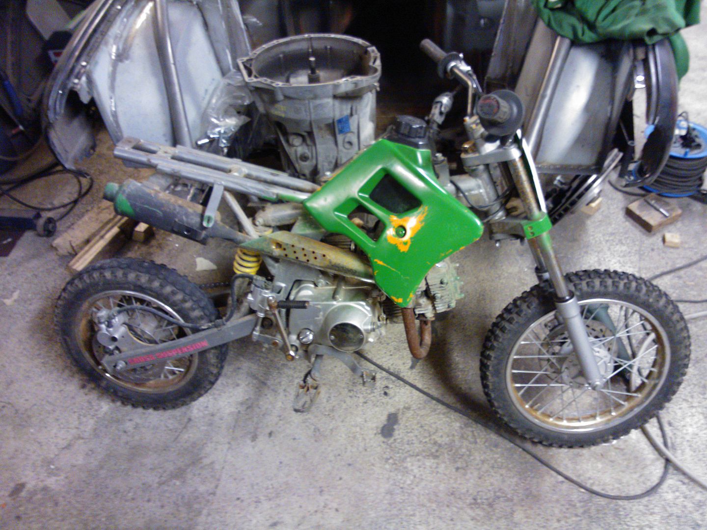 An hour or two later we modified the frame a little: 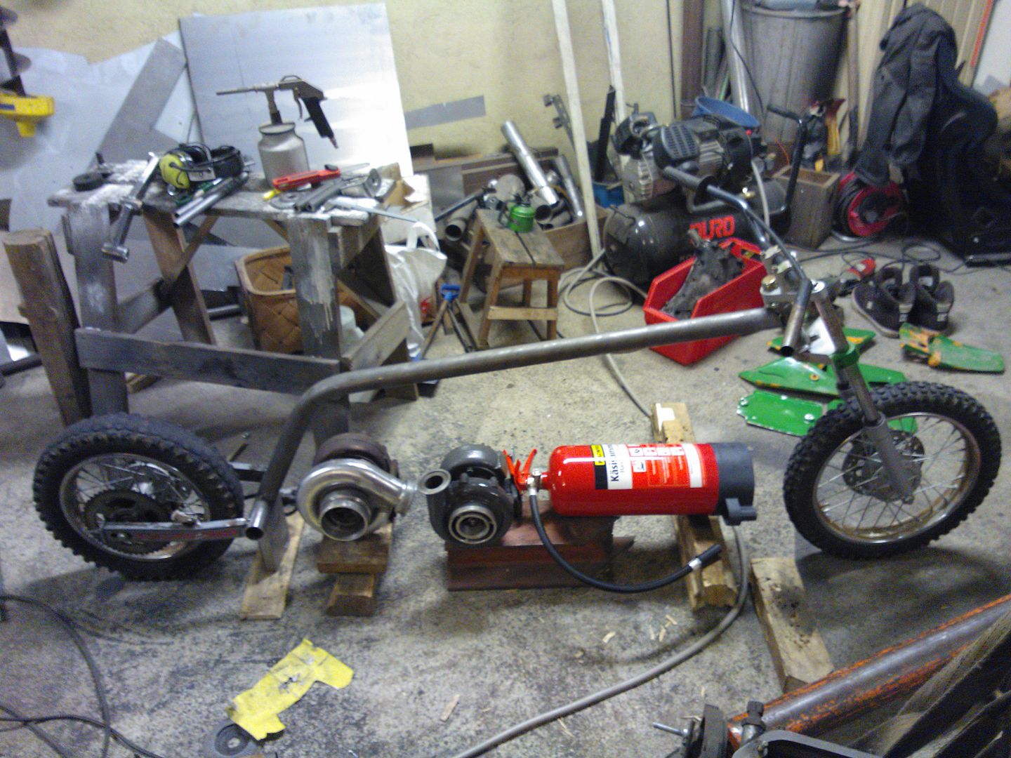 As you can see, we'd like to use a freepower turbine also. Combustor was designed with JetSpecs, known to be a decent program. Here's a few pics of the manufacturing: i187.photobucket.com/albums/x281/mice325/Project%20Jatkettu/WP_002126_zps5c8a9f3d.jpgi187.photobucket.com/albums/x281/mice325/Project%20Jatkettu/WP_002132_zpsaf1a1ff7.jpgi187.photobucket.com/albums/x281/mice325/Project%20Jatkettu/WP_002151_zps11a62af0.jpg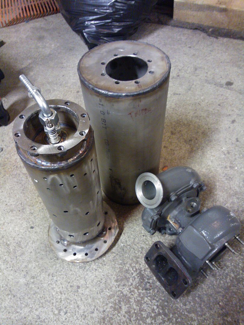 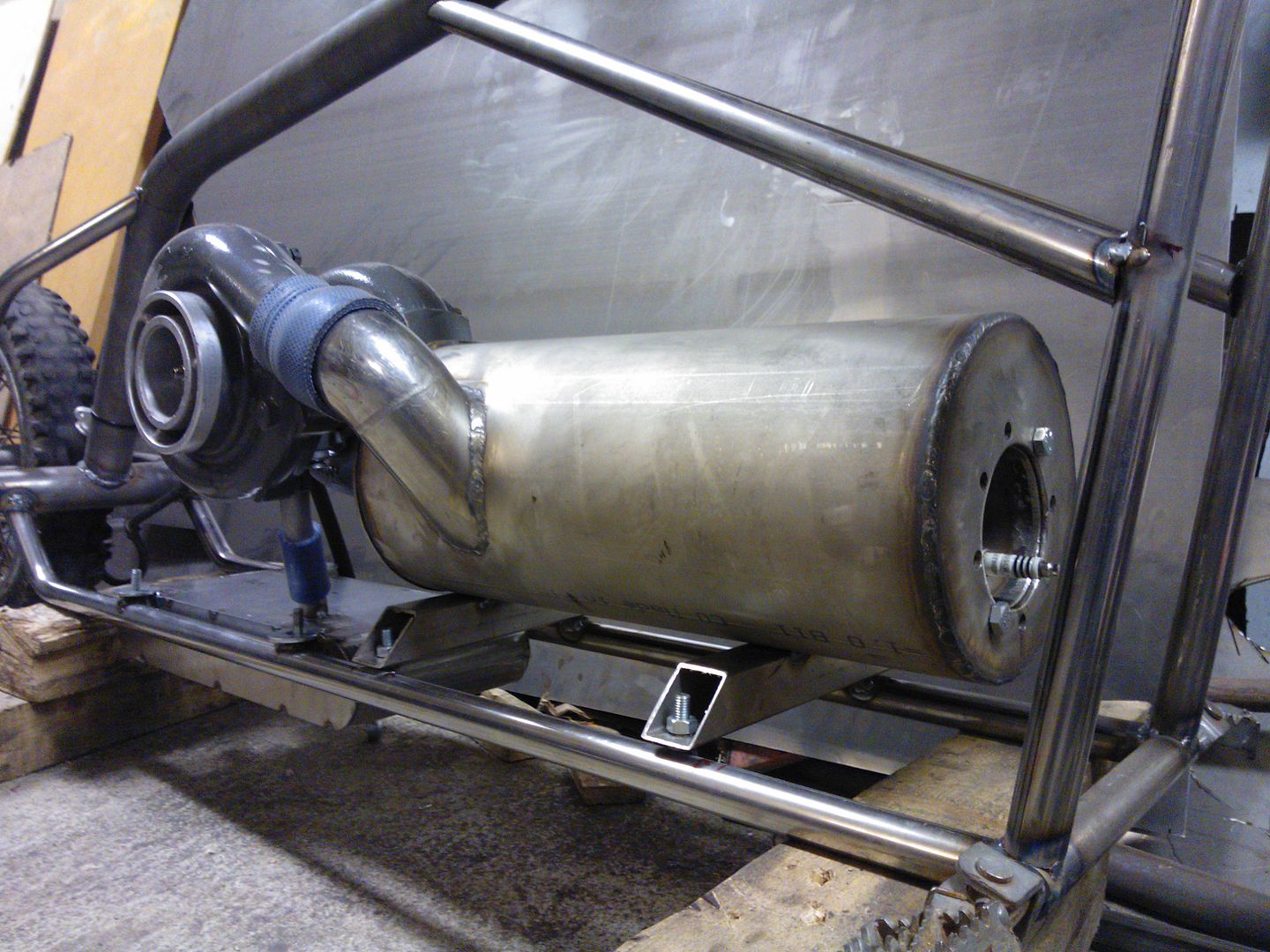 2liter oil tank: i187.photobucket.com/albums/x281/mice325/Project%20Jatkettu/WP_002215_zpsf8c4759d.jpgFew type of LPG/Propane injectors, first we used was on the right and now we are running the one in the middle (6x 1.5mm holes): i187.photobucket.com/albums/x281/mice325/Project%20Jatkettu/WP_002239_zps8d90877f.jpgFirst time running: www.youtube.com/watch?v=IalA3214p8AInside the combustor: i187.photobucket.com/albums/x281/mice325/Project%20Jatkettu/WP_002246_zps0c38b1b4.jpgAfter first tests we were tired of the push-button-piezo ignition, so I ordered a battery piezo which works well indeed: i187.photobucket.com/albums/x281/mice325/Project%20Jatkettu/WP_002366_zps3cbf1855.jpgFor further testing we also needed a EGT gauge to keep an eye on TOT, here's our great sub 20€ gauge: i187.photobucket.com/albums/x281/mice325/Project%20Jatkettu/WP_002363_zps09ce88f4.jpgi187.photobucket.com/albums/x281/mice325/Project%20Jatkettu/WP_002372_zpsc098e879.jpgThen, latest video from yesterday: 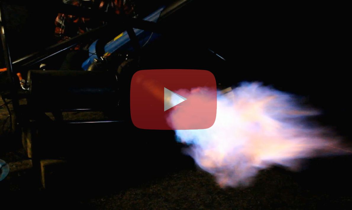 Max. propane pressure was 4bar / 58psi Max. boost / P2 was 2,8bar / 40psi Max. TOT was 780°C / 1430°F And the problems... Turbine works well with no boost, we can throttle it to very minimal revs and rise it near the zone where it starts to create pressure. But then, if it peaks even a little boost it will shut down. Doesn't matter if we use the pressure regulator or the valve to adjust the revs it will shut down with boost. Only thing how we managed to keep it running with boost was open the valve fast, seen on the video above. Then, how could we possibly make it lower the revs...  When closing the valve (when running on boost) it will shut down also.. Any tips? Thanks, Miuge |
|
|
|
Post by racket on Mar 12, 2014 17:03:48 GMT -5
Hi Miuge
Could you please clarify a few points ...........
The fuel injector looks OK with the 6 radial holes ..............is the end of the tube blanked off with no axial hole ??
What are the compressor inducer and turbine exducer diameters , also any A/R numbers on the scrolls ??
Is that boost pressure a gauge pressure or a pressure ratio , as 2.8 bar/40 psi is extremely high for a small turbo , most small turbos are designed for a max pressure of ~30 psi gauge ??
Do you have a jet nozzle on the exhaust ??
If you do , remove it , the backpressure could be enough to cause your engine to surge resulting in a flameout , especially at low pressure ratios.
Your burn pattern in the flametube looks OK as it only extends to the secondary holes .
A safe idle "boost" /P2 pressure is 5-7 psi , ~0.35-0.5 bar , anything less will potentially give you problems when trying to quickly accelerate the engine .
Just a few teething problems , hopefully easily sorted :-)
Cheers
John
|
|
miuge
Veteran Member
  
Joined: March 2014
Posts: 200 
|
Post by miuge on Mar 13, 2014 5:16:29 GMT -5
Hi John! Injector has only radial holes in it. I don't remember exact specs of the turbo, but compressor is about 55/80mm and turbine 58/70mm, turbine A/R .82. 2,8bar/40psi is a gauge pressure, that turbo came from a serial production diesel which is run by 2,0bar/30psi boost. Compressor map: i187.photobucket.com/albums/x281/mice325/Project%20Jatkettu/kompurakartta_zps12cb64b6.jpgNow we have a jet nozzle in it, it's only a few millimeters coned (52mm out, turbine outlet 58mm), earlier we ran with a straight pipe with the same problems. Idle pressure might be the problem, we haven't run it to the pressure zone when starting..? It always flames out even if we slowly try to rise the rpm to the positive pressure and the same thing when lowering the gas pressure in full rpm..  But we'll try those tips, it would be nice to get it run properly! I've seen someone using propane tank upside down, is it safe? Would it change anything if we try it too? -Miuge |
|
|
|
Post by racket on Mar 13, 2014 18:41:17 GMT -5
Hi Miuge
Thanks for the info, it helps to pinpoint the problem.
Injector OK :-)
With your P2 pressure, the low Trim comp wheel is made for higher pressures but once the efficiency gets to 70% theres not much point pushing the rpm higher as the compressor inefficiency consumes any benefits the higher pressure might provide , having looked at the map I'd suggest a max P2 of 34 lbs - 2.3 bar - 3.3 PR at ~113,000rpm , this will hopefully keep flow just within the 72% effic island , the lowered rpm will also give you a bit more of a safety margin if you accidentally over temperature the engine during these initial tests , the turb tips won't fly off as easily :-)
Keep your idle at the 5-7psi , ~0.35-0.5bar , the compressor and turb wheels will be working more efficiently than if the engine is barely above self sustain , temperatures will be highest at lower idling speeds , the temperatures generally drop a little at a P2 of ~15- 22 psi, -1 -1.5 bar, before starting to climb again as rpm go higher , its due to the comp being most efficient at the 2 -2.5 PR range .
Your turbine wheel is a bit small for the sized compressor wheel/flow , you'll need to try and keep temperatures down as low as possible to minimise the chances of surge occurring, at this early stage of development and the fact that you are having some problems , I'd remove the jet nozzle until you have the engine running reliably , its easy enough to refit once you have things doing what you want .
Don't invert the propane tank , your sized turbo only needs gaseous propane , liquid propane can be very dangerous when used on a smallish turbo , very easy to overfuel/overspeed/overtemp when using it .
You mentioned using a "regulator" for the fueling ,.........remove it ..........they are often one of the causes for engine problems , we don't need them , simply use the propane cylinder valve with perhaps a quick shutoff ball valve in the delivery line in case of emergencies .
Propane cylinder size needs to be ~10 kg size , the trusty BBQ cylinder works OK in most cases , .............if the ambiant conditions are cold , sit the cylinder in warm water to help maintain the propane vapour pressure.
Hope this helps ,....... let us know what happens when you make the changes, there could still be something else that needs modifying :-)
Cheers
John
|
|
miuge
Veteran Member
  
Joined: March 2014
Posts: 200 
|
Post by miuge on Mar 14, 2014 13:54:09 GMT -5
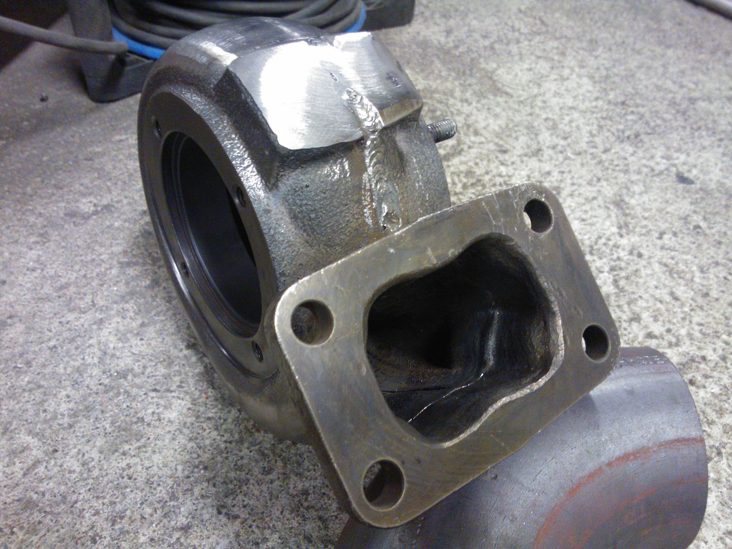
Hi, Few tests done again, with and without jet nozzle and pressure regulator. Notes; jet nozzle didn't show any change to operation. Same temperatures, same problems. Removing the regulator helped starting the turbine (operated from the cylinder valve), nothing more. We still couldn't rise rpm so it would idle at positive pressure. No matter how slowly we try to open the valve, at some point rpm start to rise and it flames out... Too much air flow which extinguish the flame? It goes too lean? We have used warm water trick for the bottle otherwise it freezes very fast  Last time we had time for only few runs opening the valve fast to get it run with boost. Today we continued the same way with different propane pressures. We got it run 2,5bar of boost which reduced TOT for over 100°C! Gauge was showing 670°C, which is good I think. Later we disassembled the turbo to see how's the heat pattern in flametube and check turbine blades. Heat pattern has come further to turbine inlet (previous picture was taken when idling without boost). Coolest spot nearest to charge pipe: 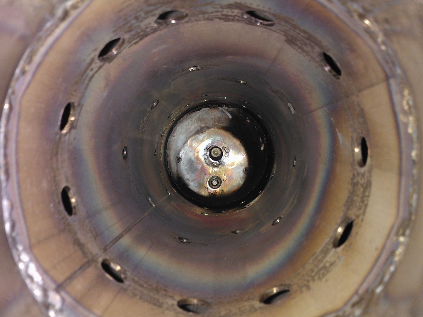 Surprise surprise! Now I know why divided housing isn't the best, luckily turbine wheel has no damage at all  I think we will make the housing single entry to avoid this kind of consequence: 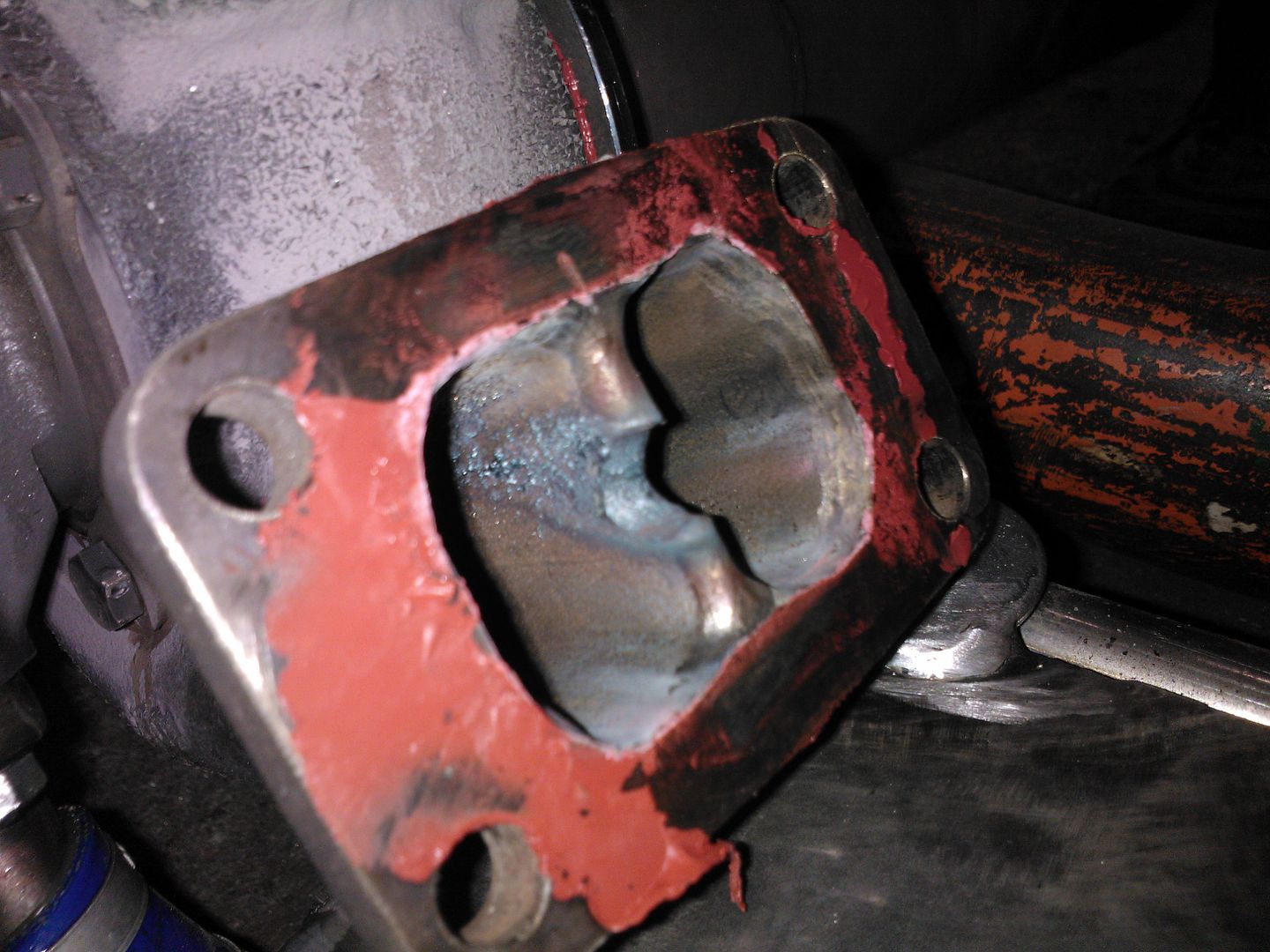
As this project is only experimental with no time limit etc.. How about converting it to run Diesel?? Could it be the answer to running problems? -Miuge |
|
|
|
Post by racket on Mar 15, 2014 0:40:27 GMT -5
Hi Miuge
Could you please post a side on picture of your flametube, I'm interested in how you've constructed the outlet end of it.
Yeh , single entry is best , that melted scroll housing spray can end up coating the turbine wheel .
Cheers
John
|
|
miuge
Veteran Member
  
Joined: March 2014
Posts: 200 
|
Post by miuge on Mar 15, 2014 5:21:43 GMT -5
|
|
|
|
Post by racket on Mar 15, 2014 19:22:14 GMT -5
Hi Miuge OK, flametube exit seems to be no problem . There is one other thing I need to ask about ..............the compressor housing inlet , is the bore between housing inlet and compressor wheel inducer parallel or is there a taper or reduction of diameter somewhere?? If we have a parallel bore with a sharp right angle lip at the front a vena contracta can develop en.wikipedia.org/wiki/Vena_contracta this has been the cause of overheating problems with our engines in the past, our engines will work better with a suitable bell mouth on the inlet to smooth flow into the compressor wheel . Could you please give me the hole sizes and number in your flametube , there could be a miss match somewhere . Cheers John |
|
miuge
Veteran Member
  
Joined: March 2014
Posts: 200 
|
Post by miuge on Mar 17, 2014 14:35:26 GMT -5
|
|
|
|
Post by racket on Mar 17, 2014 16:27:44 GMT -5
Hi Miuge
Nicely done job on that centre divide :-)
How did you get the axial distance back to standard so that the clearance between turb wheel and its shroud was the same as original, did you shim the two halves or remachine the housing ?
Hole area looks about right , might I suggest you open up 3 of those 6mm dia primary holes to 10mm diameter , equally spaced 120 degrees apart around the flametube at the same axial distance as your fuel injection holes , the larger hole diameter will provide a deeper penetrating air jet that will get into the fuel spray , the combination of a 120mm dia flametube and a "tangential" delivery tube position will produce a "vortex" that can produce air/fuel mixing problems at low fuel flow rates , the fuel simply pours down the centre of the flametube whilst the large number of relatively small primary holes only produce an airflow near the wall .
I don't like tangential air delivery tubes , they can cause problems :-(
Comp housing inlet looks better :-)
All the best with the next test run , I'll look forward to hearing the results
Cheers
John
|
|
miuge
Veteran Member
  
Joined: March 2014
Posts: 200 
|
Post by miuge on Mar 18, 2014 15:37:45 GMT -5
We used shims to keep the clearence the same  If tangential delivery tube ain't good, then it has to be fixed: 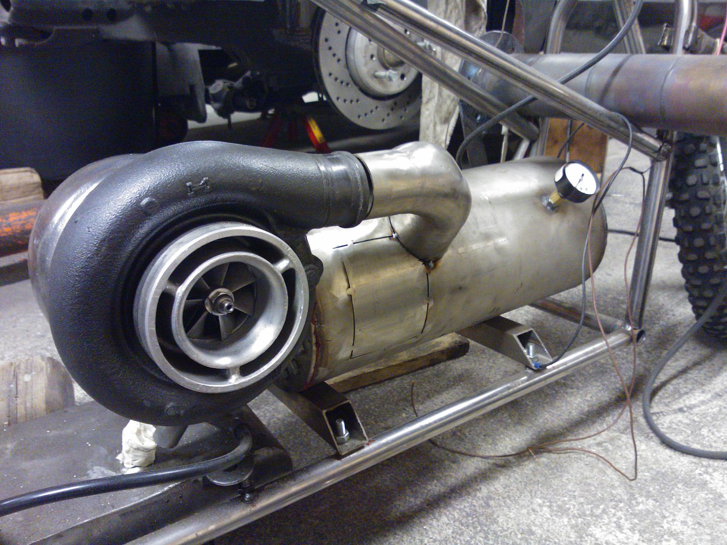 Positioned between secondary and tertiary zone: i187.photobucket.com/albums/x281/mice325/Project%20Jatkettu/WP_002432_zps2d21aa81.jpg3 of the primary holes also opened to 10mm and all holes now got a little tapering if it helps air penetration.. Should test this version by the weekend, hopefully we get better results  |
|
|
|
Post by racket on Mar 18, 2014 20:32:59 GMT -5
Looking good :-)
|
|
|
|
Post by Johansson on Mar 18, 2014 23:50:19 GMT -5
Good luck with the test!
|
|
miuge
Veteran Member
  
Joined: March 2014
Posts: 200 
|
Post by miuge on Mar 19, 2014 16:49:28 GMT -5
Thanks guys!  Some further planning before next tests.. Like I said earlier, we did some testing with an old Bosch EFI pump and 1.5GPH oil heater injector. Pump gave 7bar pressure and then it faded, at 6.5bar it ran smoothly. We modified one injector which gave about 11GPH, just to see if the pump can keep the pressure with a larger injector. And it did it good  It should be good for our purpose when converting to diesel. Injector size for maximum air flow of 50lbs/min should be 7.2GPH for my calculations and that's at 100psi/7bar fuel pressure. Then we should notice the P2 and our lower fuel pressure which means injector size should be around 8.5GPH. To be sure we got enough fuel 9.5GPH injector should be worth of testing too.. Correct me if I'm completely lost with the sizing... :--) Oil pump is also under construction, my friend will machine casing for oil pump rotors from a 150cc 4-stroke engine. An electric motor needed to power it. Then the freepower unit. We got this S300 turbo with 72mm (out) turbine wheel, had a little damage but we did grind it "better": i187.photobucket.com/albums/x281/mice325/Project%20Jatkettu/WP_002360_zpse4b4116c.jpgi187.photobucket.com/albums/x281/mice325/Project%20Jatkettu/WP_002358_zps8e7765e4.jpgClosest turbine map I could find is this Garrett GT3782 map: www.turbobygarrett.com/turbobygarrett/sites/default/files/default_images/turbogroup/performance_maps/452195-3turb.jpgAny good? Thought was to replace the compressor wheel with a sturdy planetary gear and maybe a centrifugal clutch after it... Just thinking by far  |
|
|
|
Post by racket on Mar 19, 2014 22:50:54 GMT -5
Hi Miuge Your injector sizes are about right but you need to adjust them for the possibility that the mass flow might be reduced a bit by the rather small turbine stage , I'd be inclined to start with a spray nozzle of ~4-5 GPH , this will have better atomisation and as the flow is reduced theres less chance of an overfuel/overspeed situation occurring until you've had a chance to run it and familiarise yourselves with using liquid fuel. Oilpumps .............you'll be needing a reasonably large flow if you also intend feeding the freepower bearings , I've used Subaru oilpumps from the early pushrod motors , this type pump www.ebay.com/itm/ITM-Engine-Components-057-620-New-Oil-Pump-/171269174489?pt=Motors_Car_Truck_Parts_Accessories&fits=Make%3ASubaru%7CModel%3ABrat&hash=item27e07034d9&vxp=mtrit has oil filter as well as pressure relief valves etc, they flow ~9cc/revolution of the pump . The freepower sizing will depend on what sort of flow/pressure/temperature is exiting the gas producer., the S300 might be a bit marginal , ideally you need to measure your gas producer output parameters to determine the corrected flow and check the turbine performance map for suitability . My 2 shaft karts freepower jetandturbineowners.proboards.com/thread/40/2-shaft-turbine-kart-build was suitable for ~66 lbs/min - 1.1 lbs/sec flow with its 3.5" turb exducer outlet diameter . Cheers John |
|


 When closing the valve (when running on boost) it will shut down also.. Any tips?


 When closing the valve (when running on boost) it will shut down also.. Any tips?


