miuge
Veteran Member

Joined: March 2014
Posts: 199 
|
Post by miuge on May 18, 2014 8:21:18 GMT -5
We use a shim plate between the turbinewheel and bearing so that bearings' inner rings, center sleeve and the sleeve for the sprocket are one joint, then the lock nut tighten the whole package.
|
|
|
|
Post by madpatty on May 18, 2014 9:38:58 GMT -5
Its too complex understanding...
Sorry but weak at this....can you explain in a bit easy language or a drawing..??
|
|
|
|
Post by madpatty on May 18, 2014 9:42:44 GMT -5
Also how to lock that sleeve on the shaft...??
|
|
|
|
Post by madpatty on May 19, 2014 11:24:41 GMT -5
Hi Guys,
This may sound stupid but can sprocket sleeve be locked against the BUMP(where the diameter of turbine shaft decreases to accept compressor wheel) WITH A LOCK NUT pushing sprocket sleeve against that bump...
Is that few millimetres change in cross section strong enough to hold the sprocket???
|
|
miuge
Veteran Member
Joined: March 2014
Posts: 199
|
Post by miuge on May 19, 2014 16:22:55 GMT -5
Not sure about that.. How do you lock turbineshaft's axial motion then? Today I made a bracket for the powerturbine:  We got a 120/70-12 rear tyre, it's a bit streched but we couldn't find any better for our budget: 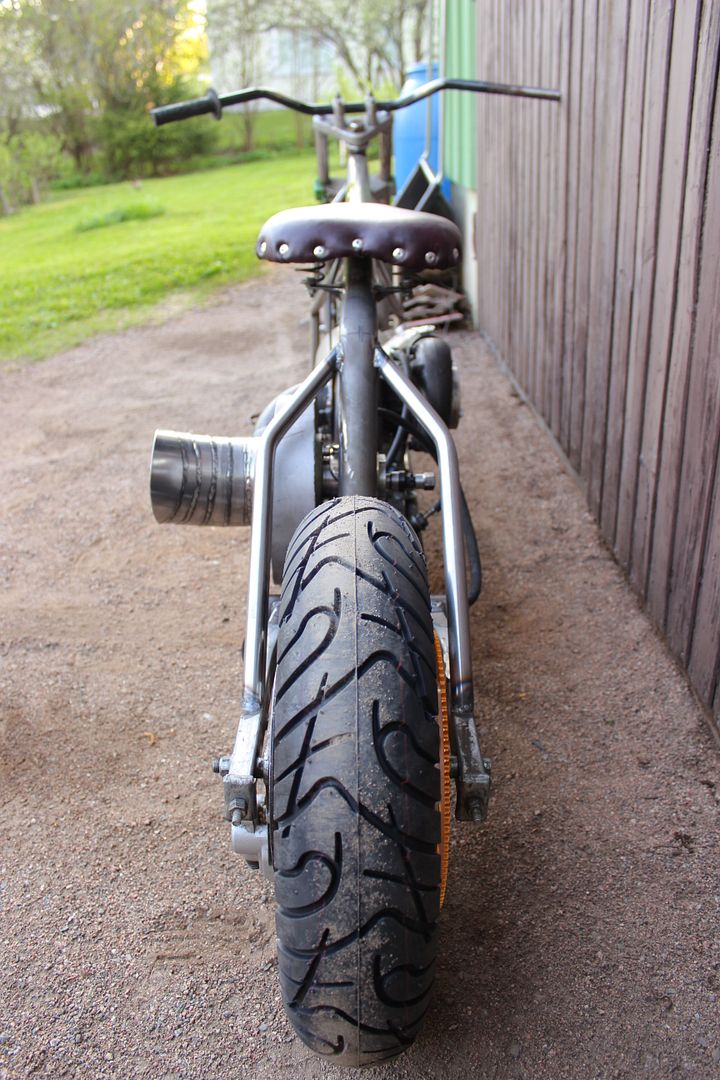 i187.photobucket.com/albums/x281/mice325/Project%20Jatkettu/IMG_3644_zps7dca7040.jpg i187.photobucket.com/albums/x281/mice325/Project%20Jatkettu/IMG_3644_zps7dca7040.jpgI started to create fuel tank of a 170mm aluminium pipe, battery sits nice in front of the tank: 
Spent a moment with photoshop, what do you think? 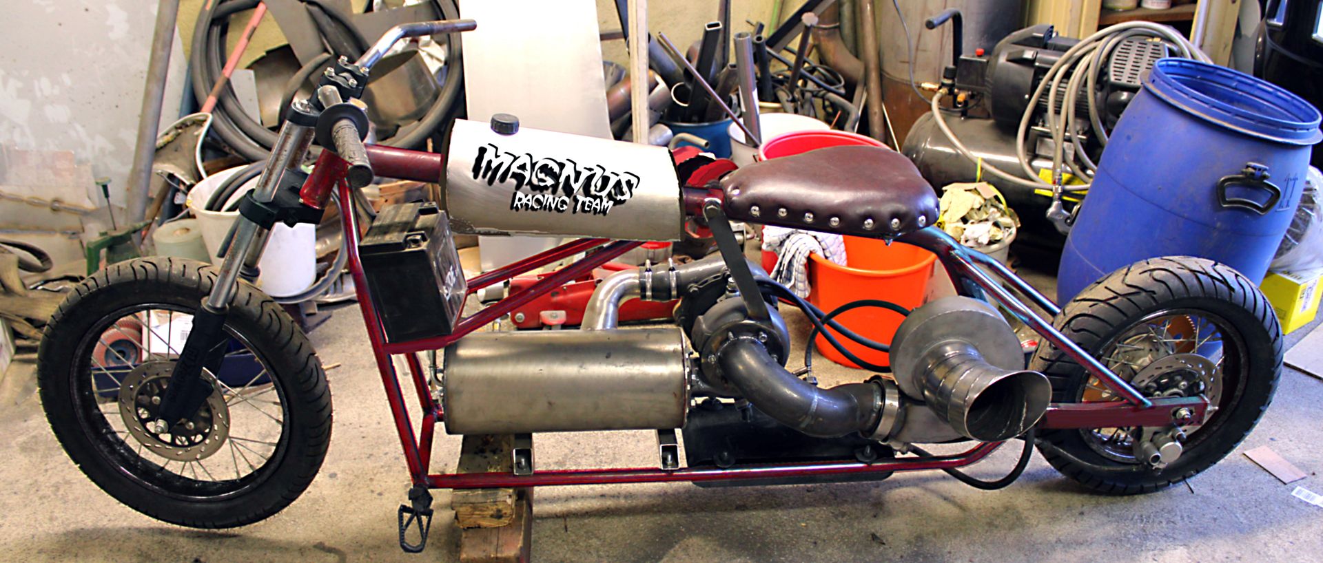 |
|
|
|
Post by racket on May 19, 2014 19:02:10 GMT -5
Love it :-)
|
|
|
|
Post by Johansson on May 19, 2014 22:59:49 GMT -5
It look wicked!  How much are you restricting the oil to the S500 shaft bearings? I see you bleed it off the main oil line to the engine. |
|
miuge
Veteran Member
Joined: March 2014
Posts: 199
|
Post by miuge on May 20, 2014 2:07:00 GMT -5
Thanks again!
I don't know yet how much it will be restricted, we'll make it adjustable, so the x-amount bleed oil will circulate through powerturbine. Is there any disadvantage if we put the oil feed line on bottom and return to the top, it would give better lubrication as the CHRA would be filled with oil..
|
|
|
|
Post by racket on May 20, 2014 4:06:33 GMT -5
With return from the top , you'll potentially have oil bypassing your turbine piston ring seal once the shaft tunnel is full of oil even when the oilpump is deactivated .
|
|
|
|
Post by finiteparts on May 20, 2014 21:01:36 GMT -5
It's looking good!
In addition to Racket's concern, I would also think that the churning action of the rotating balls and cage in each bearing would aerate or froth the oil up and limit your ability to drain the oil out. That is why the turbo center housing uses a larger drain line. Journal bearings don't aerate the oil much more than ball bearings...So, you might want to make your drain from the free turbine bearing housing larger to accommodate the aerated oil and maybe rotate it lower so that you don't have so much oil in your bearing housing.
Generally speaking, you want the oil level in a ball bearing housing to not go any higher than the center line of the lowest ball...by letting the oil fill higher you increase the oil churn and create excess heating. You'd be better off making some small oil jets that direct the oil to the bearings and then draining from the bottom. This would be less sensitive to the orientation of the bearing housing, which could conceivably have one of the bearings experience a low oil level in a turn.
~ Chris
|
|
|
|
Post by racket on May 20, 2014 21:29:46 GMT -5
When I made the bearing housing for the 2 shaft kart I only had a few drips of oil per minute being fed into the shaft tunnel at the furthest point from the turbine wheel, bleed air was fed to an air seal around the output shaft near the sprocket where it exited back into the shaft tunnel, picked up the few drops of oil and blew them through the 2 bearings and into the turbine scroll where they exited with the exhaust gases .
The bleed air kept oil from leaking out behind the sprocket and kept hot gases from entering the shaft tunnel as well as cooling the turbine wheel reducing soak back of heat into the turbine end bearing , there wasn't any seal on the turbine shaft just a healthy running clearance for the oil/air mix to exit through .
Oil tank breather fumes were plumbed to lubricate the chain .
Cheers
John
|
|
miuge
Veteran Member
Joined: March 2014
Posts: 199
|
Post by miuge on May 21, 2014 1:10:20 GMT -5
Good to know! We'll try first feed line on top so there won't be much oil in the bearing housing, then the return is somewhat the same level as the bottom of bearing housing. Yesterday I was thinking where should I put the oil breather hose.. now I know  I also made an adapter for the front brake, my friend found a suitable Honda NS125R caliper from his stash. Rear brake will be operated from the clutch lever.. |
|
miuge
Veteran Member
Joined: March 2014
Posts: 199
|
Post by miuge on May 23, 2014 16:09:49 GMT -5
Instrument panel with gauges for fuel pressure, oil pressure, TOT and P2, still need one gauge for power turbine pressure. Our machinist made a sleeve for a tank cap. Also we got a "new" 30Amp battery: 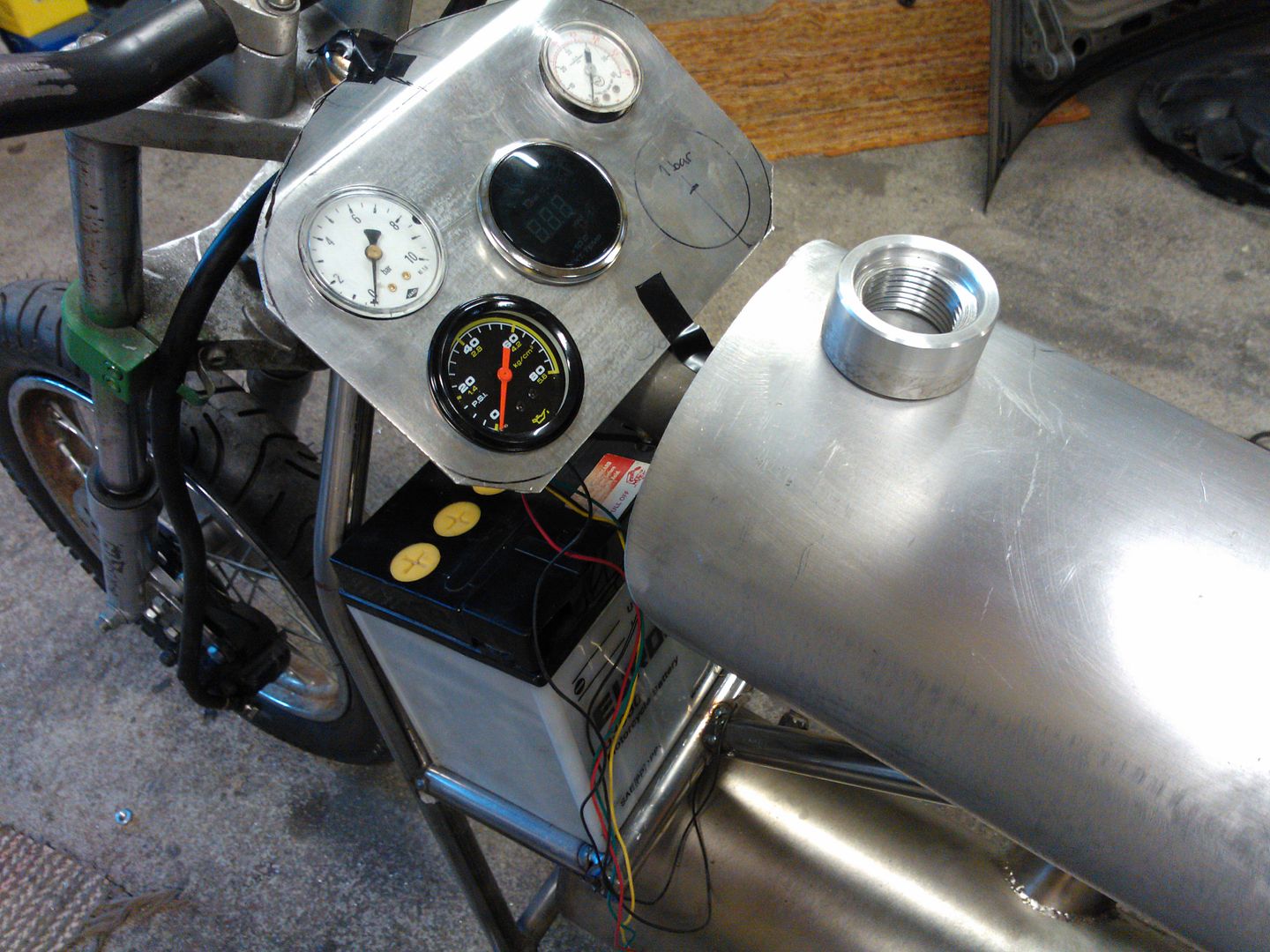 Middle stand, no more need for a wooden rack, bricks whatsoever: 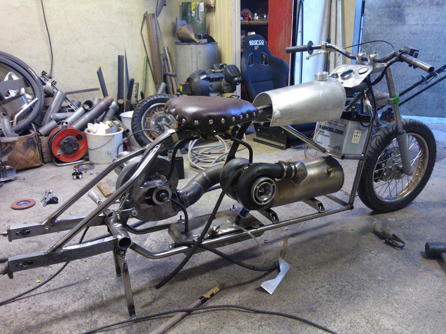 |
|
|
|
Post by madpatty on May 25, 2014 1:21:02 GMT -5
Hi Miuge, Good to see your project advancements... I wanted to know how are preventing lubricating oil from leaking on both sides of the bearing housing(sprocket end and hot end)  |
|
miuge
Veteran Member
Joined: March 2014
Posts: 199
|
Post by miuge on May 25, 2014 5:59:16 GMT -5
As you can see there's an oil seal behind the sprocket and original piston ring seals turbine end. Video clip of "drivetrain" manufacturing: vimeo.com/96170633 |
|


