|
|
Post by Johansson on Dec 19, 2010 7:20:39 GMT -5
Thought I should start a thread about my "real" project that I´ve been working on for a year now, it is based on a TV94 turbo rotor just like John Wallis engine and John has been a great mentor during the build giving me lots of advice on tolerances and such. 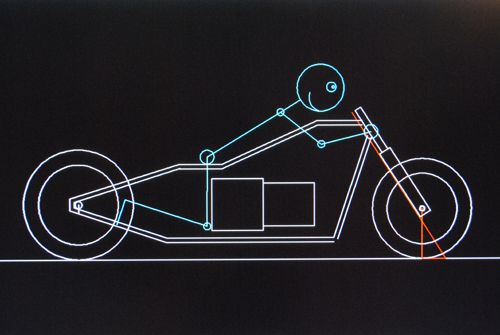 The idea is to build a landspeed bike around the engine from chromemoly tubing and try my luck at the local speed events, if things go as planned I might ship it to England for some flying kilometer racing and perhaps even take it all the way to Bonneville some day. 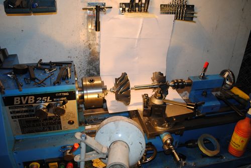 The engine is calculated to produce 54kg of thrust and with a suitable power turbine and 6:1 gearing it can perhaps produce 150hp on the rear wheel, slightly more with methanol/water injection. I am building everything myself on a manual lathe and mill so no CNC-machining here. 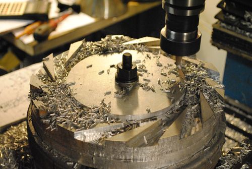 The compressor wheel is a piece of art, I´ve even ordered a spare one just to keep in my bookshelf. =) 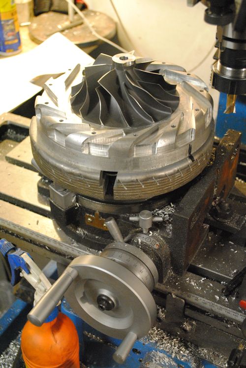 More milling on the backside of the compressor diffusor plate, I have made aproximately 60 hours of machining on this part alone. 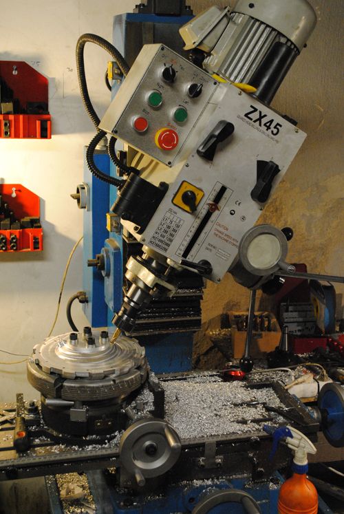 Some fine tuning in the lathe to take the final cuts behind the compressor wheel. 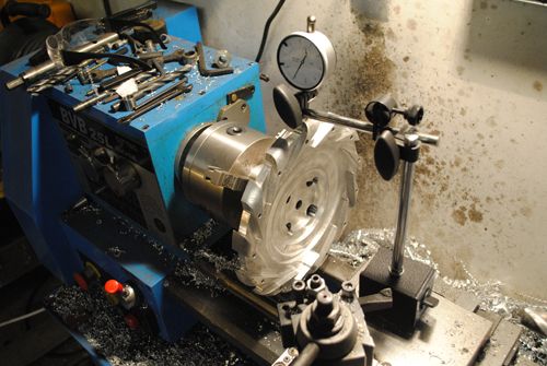 Milling the thrust bearing surface. 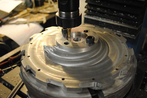 Grinding the inner radius by hand, I itched an entire day afterwards from the bozillions of small aluminum needles in my hair and arms...  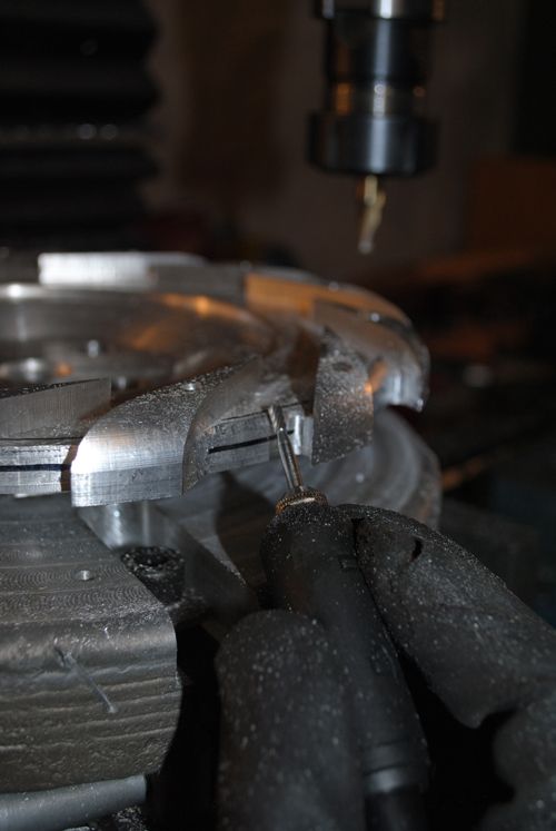 Here is the result: 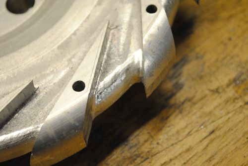 Drilling the oil channel to the thrust bearing. 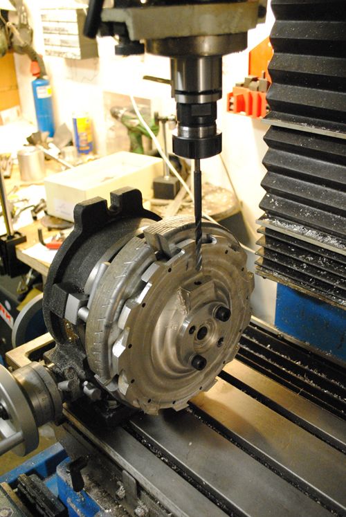 The backside of the thrust bearing. 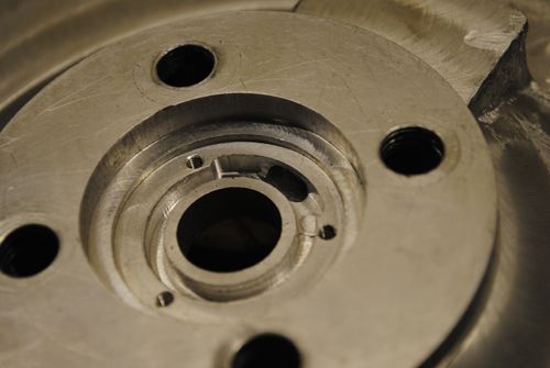 Thrust bearing fitted. 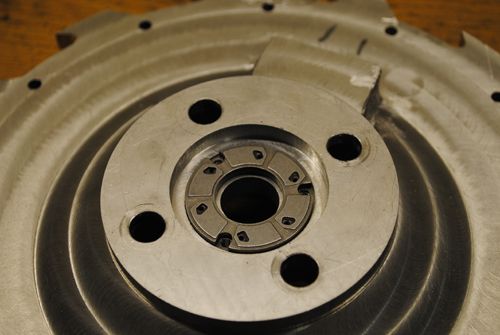 Next up is the bearing tunnel, but that will be in the next post to keep it readable.  |
|
|
|
Post by Johansson on Dec 19, 2010 16:05:55 GMT -5
To make the bearing tunnel I asked a local casting company if they could cast a solid chunk of aluminum for me since we hadn´t finished our homemade forge at that time, a couple of weeks later I got it. 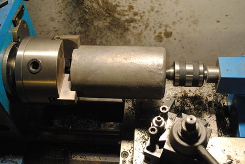 After some work on the lathe it started to look like a bearing tunnel. 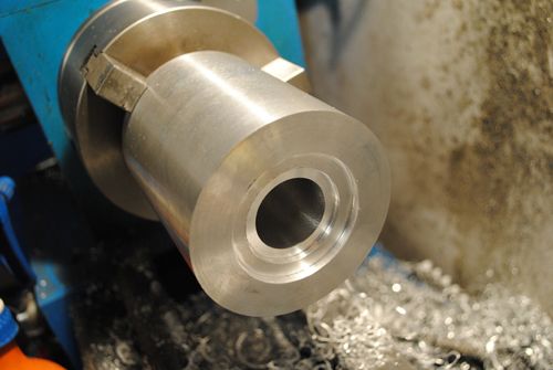 After drilling and tapping the four holes and milling a slot for a gasket I could bolt the shaft tunnel together with the diffusor plate, this was in the middle of last summer. 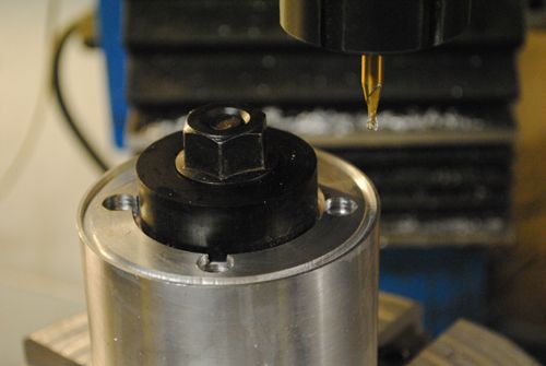 Here is a picture with the turbine shaft mounted in the tunnel. 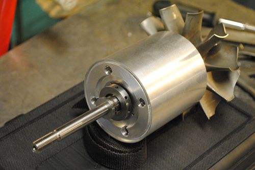 At this time I got a steel disc cut out that was going to become the turbine plate. 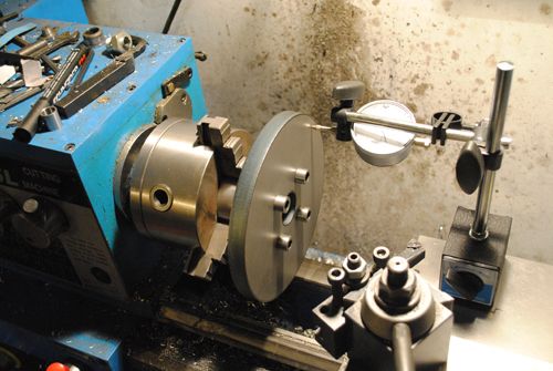 With all bearing tolerances ok I could assemble the entire shaft for the first time, felt really good to finally see it together. 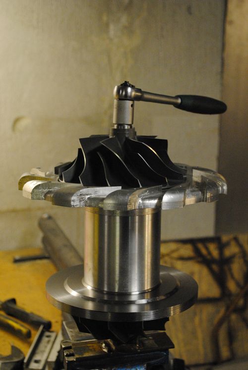 Next up is making the oil gallery for the bearings! |
|
|
|
Post by ernie wrenn on Dec 20, 2010 8:39:54 GMT -5
WOW! That is some fine hand machining.
Ernie
|
|
|
|
Post by Johansson on Dec 20, 2010 14:28:04 GMT -5
Thanks Ernie! I have had to manifacture many custom tools and mounting jigs for this build, for example I made some sort of arbor mill bit to make an oil sump inside the bearing tunnel. 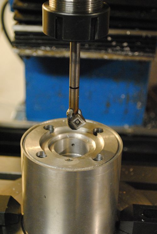 And the result: 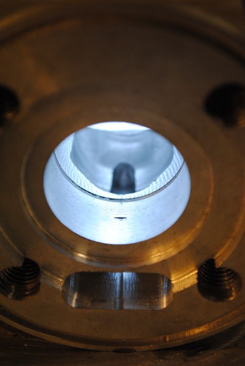 Here is another tool I made to cut the lock ring grooves. 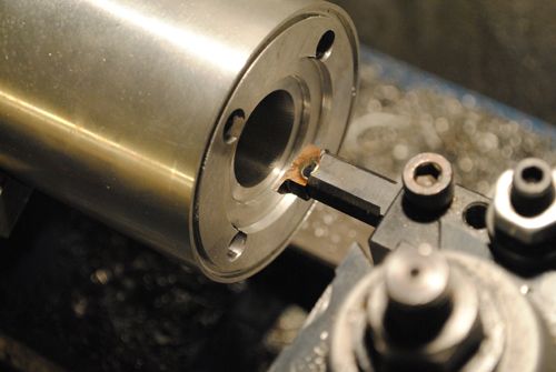 With that done I milled the material away where the oil lines were going to be. 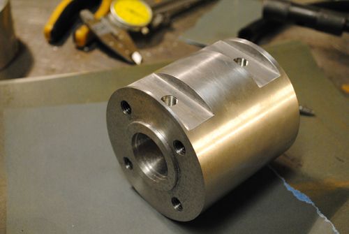 Started to make the oil lines. 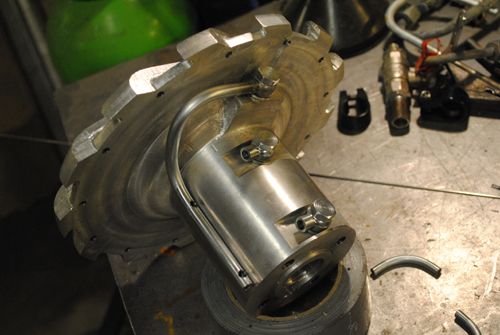 More work... 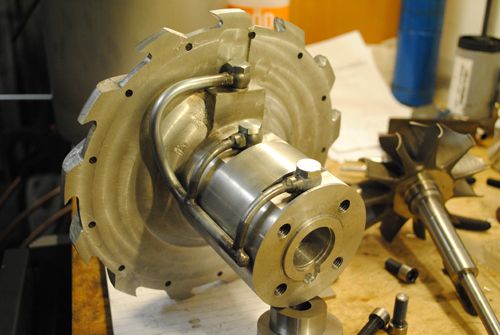 ...and more... 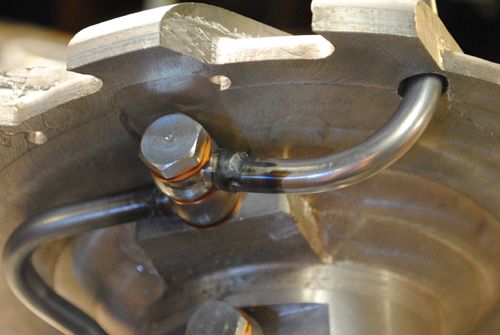 ...and with the oil return line made it was finished! 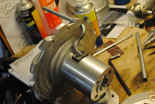 Now I could assemble the core and get some oil flowing through the bearings, it was interesting to see if it would leak somewhere. 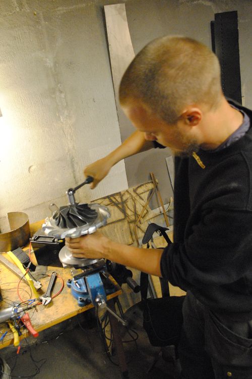 I use a 12V Flojet oil pump and a 12V gear pump to suck the return oil out from the sump, unlike Racket´s engine I haven´t got enough free fall and return line diameter for our friend Gravity to do the job so a scavange pump is needed. 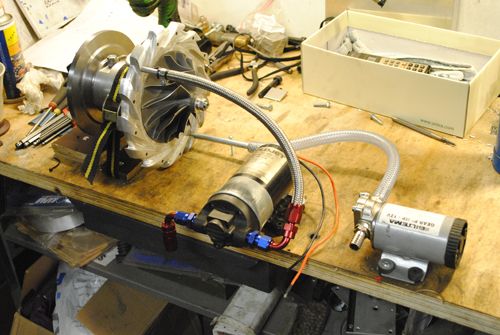 The test gave very positive results so with that done it was time to see if I could cast a housing for the compressor wheel! |
|
|
|
Post by ernie wrenn on Dec 20, 2010 15:26:21 GMT -5
Damn.. I just have to make a few custom pieces and modify everything else on the vehicle ... Great work  . Ernie |
|
|
|
Post by Johansson on Dec 20, 2010 15:56:22 GMT -5
I built a furnace with my friend who owns the jet kick and gave it a go, earlier this year we did an attempt to cast a part in a coal burning furnace but oily aluminum parts and not enough heat produced cavities in the casting so I used that part as a mounting jig on my rotary table. This time the casting turned out to be ok, after it had cooled down for a day I could remove it from the mould. The idea was to make the part that follows the compressor wheel profile from it. 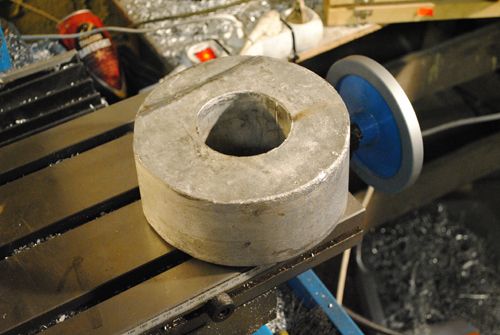 Before I could do anything with the casting I had to anneal it in the kitchen oven for 12 hours, that treatment made wonders to the machinability (is there such a word?) since it gave off small chunks of aluminum earlier while milling in it. 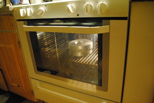 Now I had to manifacture the lid over the diffusor plate, I had to do that part first before I could continue on the compressor cover. 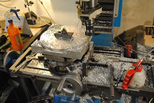 This was very tedious work, hours and hours of turning the rotary table... 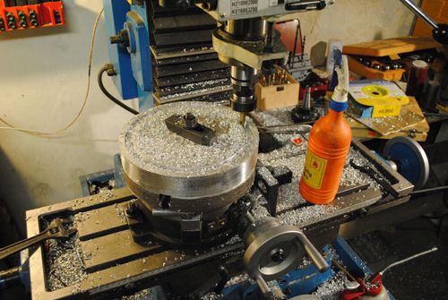 To make the radius I tried to use cheap wood mill bits, they work great and saved me lots of money since "real" metal radius bits are quite expensive. 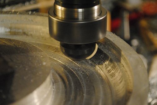 The final result with the diffusor plate in place, a snug fit. 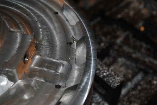 Milling the outside of the diffusor lid. 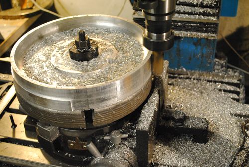 After that I turned the part over and removed the centrum to make place for the cast compressor cover. 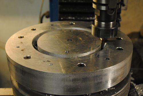 Here is a picture of the lid bolted to the diffusor plate with the compressor wheel in place. 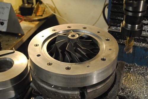 Another DIY mill bit, I made it to make the compressor wheel radius in the cover. 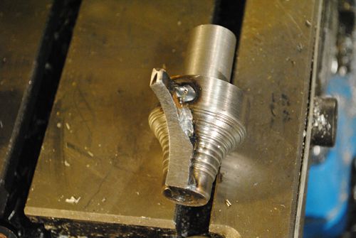 Just about to start milling in the cast compressor lid, as you can see I had spent some time working on it in the lathe before this. 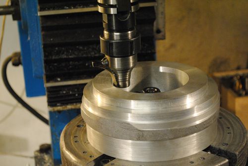 Milling... 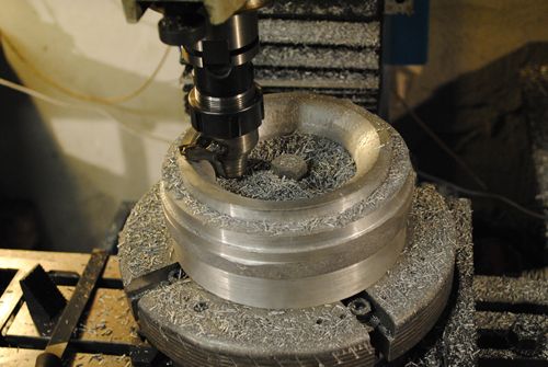 And done! 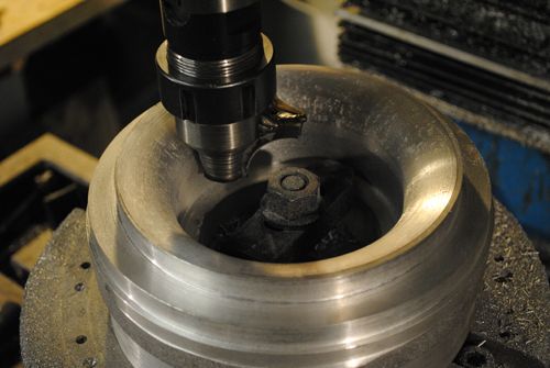 To get the right fit I had to take the final cuts by hand, with the cover in the lathe, a hand held grinder and a couple of hours of work I got the tolerances right. 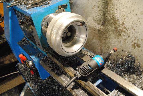 The fit: 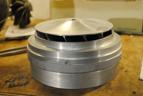 Here is a picture of the compressor cover in place in the diffusor cover. 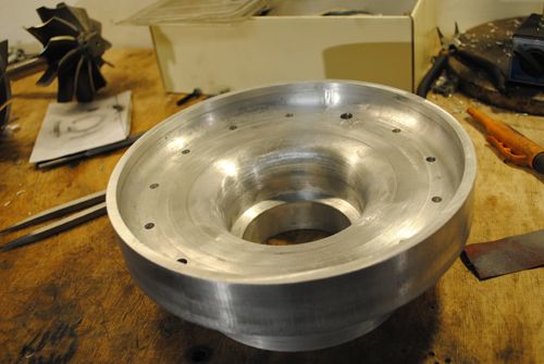 The front of the compressor cover was then radiused in the same way as the inside. 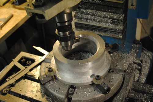 Test fitting: 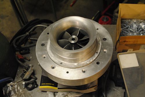 Here is the finished part after some more work, John has pointed out that a couple of more bolts holding the compressor cover could be needed so I´ll look into that. 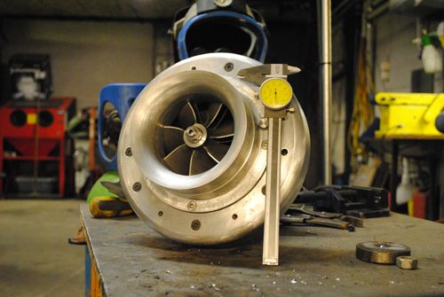 Next up, the turbine housing! |
|
|
|
Post by racket on Dec 20, 2010 17:21:30 GMT -5
Hi Anders
Nice work :-)
You do a much better job of machining than me .......I'm jealous ;-)
cheers
John
|
|
|
|
Post by Johansson on Dec 21, 2010 10:27:00 GMT -5
You are too kind, John!  Anyway, the entire turbine housing will be made from mild steel and then sent away to be coated with cheramics. Much easier to manifacture it in mild steel than stainless and it will be an interesting experiment since no other DIY:er that I´ve heard of has done it before. 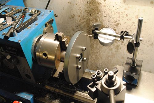 After some work in the lathe... 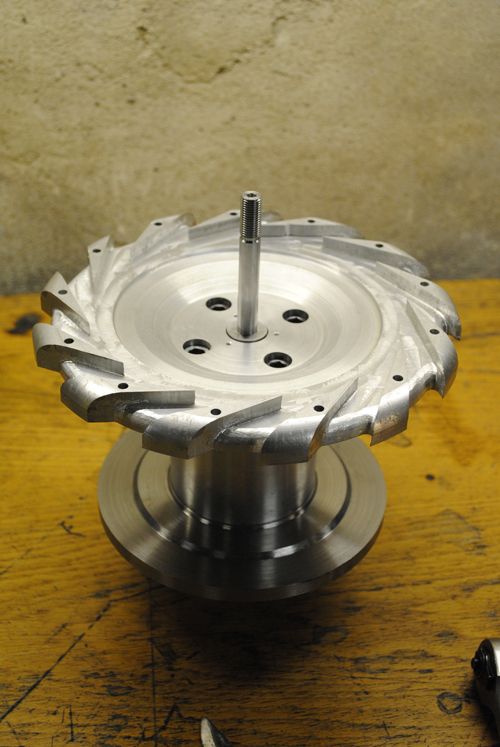 As you can see the updates are not exactly following a set time line, I have been working on several parts at the same time but it is easier to follow the progress if I keep the different parts separated like this. Here I am milling the NGV slots in the turbine disc, I even made a video that evening. 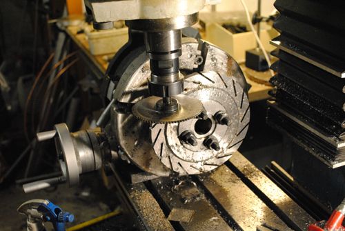 And here is the turbine shaft test mounted with the NGV slots pushed in place. 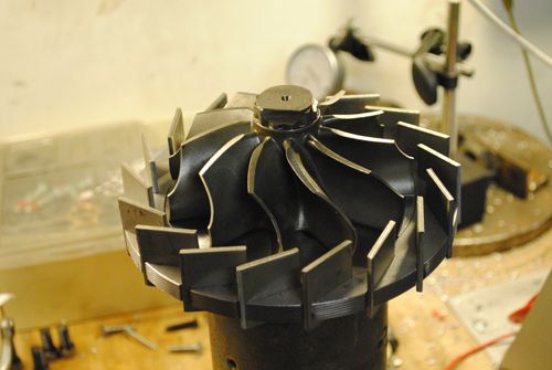 Here are some pics of the NGV manifacturing. 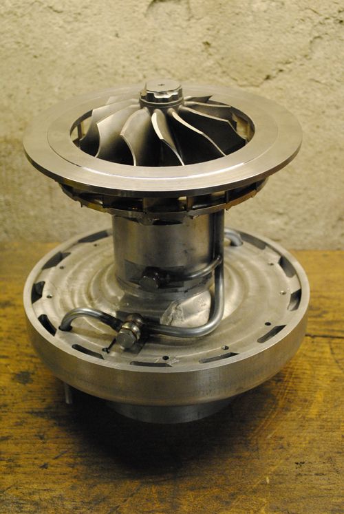 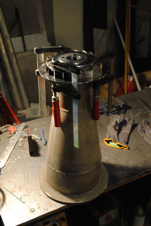 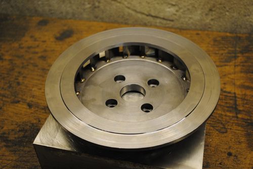 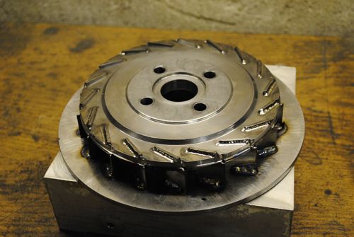 With everything welded I assembled the engine to see how everything turned out. 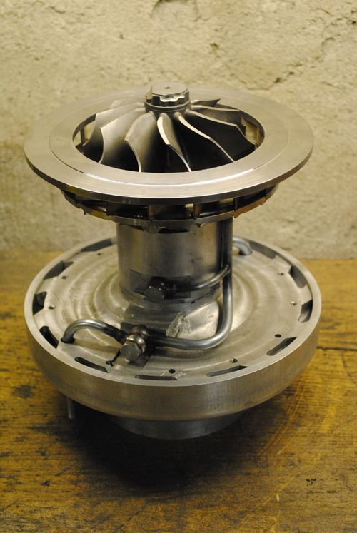 Now it was time to make the turbine cover, a 30mm steel plate was cut out by a friend on a cnc-plasma cutter and given to me as a christmas gift. =) 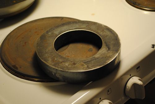 Up in the lathe with it! 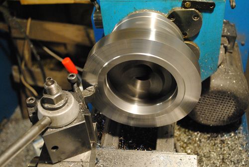 Here is the part test mounted on the engine, this is as far as I have come on the project so after the holiday I will continue making the turbine blade radius fit. 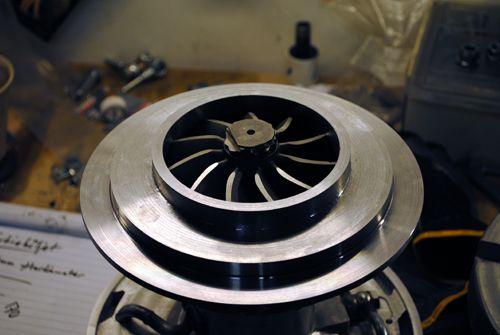 Cheers guys and have a great holiday! |
|
|
|
Post by ernie wrenn on Dec 21, 2010 11:53:52 GMT -5
I think the hand signs are universal.. How do you hand sign "Oh Sh#t" and damn?
I did notice the mill needs a good cleaning, to keep precise measurements! A free plane ticket and I will clean it for you..
Hold up! What is the temp there? if it is below 40f , wait till the summer.
Happy holidays ya'll !
ernie
|
|
|
|
Post by Johansson on Dec 21, 2010 12:01:09 GMT -5
I think the hand signs are universal.. How do you hand sign "Oh Sh#t" and damn? I usually wave my hands around and run home. ;D Hold up! What is the temp there? if it is below 40f , wait till the summer. You are very welcome! Just make sure you bring a Viper or two to blow the dust of the mill table.  You would love it here, at the moment it is -18.4°F or -28°C. It bites the nose a bit while I am taking my daily 30 minute walk to work... |
|
|
|
Post by Richard OConnell on Dec 21, 2010 14:47:17 GMT -5
Love the machine work  How much time would you figure it took to do the work so far? |
|
|
|
Post by Johansson on Dec 21, 2010 15:28:57 GMT -5
Love the machine work  How much time would you figure it took to do the work so far? Thanks! I´ve actually counted the hours spent in the workshop, 126 hours so far. For the time gathering material and planning how to build the engine you can probably add a zero...  |
|
|
|
Post by racket on Dec 21, 2010 17:32:13 GMT -5
Hi Anders
LOL.....only 126 hours , .......you're a fast worker ;-)
With your scavange pump , it'll need to have a flow rate of maybe 4 times the supply pump to cope with aerated oil and any blowby gases/air thru the seals .
Cheers
John
|
|
joe0545
Member
 
Joined: August 2010
Posts: 15
|
Post by joe0545 on Dec 21, 2010 21:52:58 GMT -5
Hey Anders , its really good to see all these pics in one place I have seen most of this before over at mobacken but its a treat to see it all here and with english subtitles ;)an excellent job and top class machine work , thanks for taking the time to document this , an inspiration !
|
|
|
|
Post by pitciblackscotland on Dec 22, 2010 1:09:05 GMT -5
Hi Anders,
I can not see the pics on this site can you tell me where to find them?.
Cheers,
Mark..
|
|