|
|
Post by racket on Jul 25, 2014 17:45:07 GMT -5
Hi Ralph Our flametubes aren't the cause of the high temperatures, both Anders and my 10/98 flametubes are basically the same, heres a pic of my flametube jetandturbineowners.proboards.com/attachment/download/44 , because we are using the original turbocharger shaft length our flametubes need to be rather short, the main body of the flametube is only ~75mm long , hence the need for the dilution to be very close to the end of the flametube , BUT , as we are running a radial inflow wheel rather than the usual axial type of most micro turbine engines including the KJ66 we have the additional distance between the end of the flametube and the exit from the radial inflow NGVs for mixing to take place. Theres video of my 10/98 engine tests on my Youtube page www.youtube.com/channel/UCHWNGFJ7enlzhsguJJbahyg if you'd like to checkout the jetpipe temperatures of less than 550 C with the engine equipped with a suitable sized jet nozzle www.youtube.com/watch?v=lrLN7idx2V8&index=6&list=UUHWNGFJ7enlzhsguJJbahyg . Since the 10/98 engine was fitted with a similar sized freepower turbine wheel as Anders has , the temperatures have climbed to over 700 C at idle . Temperature rises have nothing to do with the flametube , only to the restriction downstream of the gas producer turbine , any increased restriction lowers the available pressure drop across the gas producer turbine and the only way the engine knows how to compensate for that "energy drop" is to increase temperatures to restore the power required by the compressor wheel . Cheers John |
|
|
|
Post by finiteparts on Jul 25, 2014 21:35:57 GMT -5
Anders,
Have you checked the exit area on your exhaust stacks vs the exit area of the turbine? I would suspect that because you are turning a potentially swirling flow through 90 degrees, you might be getting a poor discharge coefficient on the two exhaust pipes (Cd < 0.7). If your exhaust area of the stacks is not much larger than the turbine exhaust area, you might have a restriction there because of the flow losses due to the flow turning and any residual swirl after the turbine are reducing your effective flow area (Effective flow area = Cd * Geometric flow area, where Cd = the discharge coefficient). Just a thought...kind of a long shot, but the fact that the flow is diffusing makes flow losses that much more likely, so it's at least worth a look.
Is your temperature an inter-turbine temperature (ITT, mounted just after the gas producer turbine, but before the power turbine) or a TOT?
That video is really nice! The bike seems to really "want" to go! Like a bull ready to charge! You have really created a functional piece of artwork there! Congrats again!!!!
~ Chris
|
|
|
|
Post by racket on Jul 26, 2014 1:16:00 GMT -5
Hi Chris A freepowered turbine bike is a "beast" wanting to run, the acceleration is like an aircrafts , starts slowly and just builds and builds in a smooth progression , no jerky gear changes, just unadulterated acceleration ...................this is how a 110 hp turbine bike accelerates www.youtube.com/watch?v=P-5PgWqgIJo ..................Anders bike has 40% more power and should weigh less than this bikes 280 Kgs and with his streamlining the top end drag will be significantly reduced allowing even better acceleration from the 100 kph point...........he won't be disappointed :-) Cheers John |
|
ripp
Veteran Member
 I'm sorry, I don't speak english, so I torment you (and myself) with a translation program,Sorry
Joined: January 2013
Posts: 231
|
Post by ripp on Jul 26, 2014 2:29:02 GMT -5
Hi Ralph Our flametubes aren't the cause of the high temperatures, both Anders and my 10/98 flametubes are basically the same, heres a pic of my flametube jetandturbineowners.proboards.com/attachment/download/44 , because we are using the original turbocharger shaft length our flametubes need to be rather short, the main body of the flametube is only ~75mm long , hence the need for the dilution to be very close to the end of the flametube , BUT , as we are running a radial inflow wheel rather than the usual axial type of most micro turbine engines including the KJ66 we have the additional distance between the end of the flametube and the exit from the radial inflow NGVs for mixing to take place. Theres video of my 10/98 engine tests on my Youtube page www.youtube.com/channel/UCHWNGFJ7enlzhsguJJbahyg if you'd like to checkout the jetpipe temperatures of less than 550 C with the engine equipped with a suitable sized jet nozzle www.youtube.com/watch?v=lrLN7idx2V8&index=6&list=UUHWNGFJ7enlzhsguJJbahyg . Since the 10/98 engine was fitted with a similar sized freepower turbine wheel as Anders has , the temperatures have climbed to over 700 C at idle . Temperature rises have nothing to do with the flametube , only to the restriction downstream of the gas producer turbine , any increased restriction lowers the available pressure drop across the gas producer turbine and the only way the engine knows how to compensate for that "energy drop" is to increase temperatures to restore the power required by the compressor wheel . Cheers John
Hi John,
I can see you have no space for a larger CC
but Anders can take away the air splitter and gaining space for a longer CC
before the engine does not reach max. speed / pressure
and a maximum 650 degree without nozzle it is not ready for
free power engine .
just my assessment!
regards
Ralph
translate.google.at
|
|
ripp
Veteran Member
I'm sorry, I don't speak english, so I torment you (and myself) with a translation program,Sorry
Joined: January 2013
Posts: 231
|
Post by ripp on Jul 26, 2014 3:15:15 GMT -5
John turbine  Anders  |
|
|
|
Post by racket on Jul 26, 2014 3:15:17 GMT -5
Hi Ralph
Both Anders engine and my 10/98 engine would have no problems running at less than 500 degree C temps without a jet nozzle/freepower downstream , my 10/98 engine was running at quite reasonable temperatures during its last pure jet test ................heres an excerpt from the summary ..............
........ A couple of short burst were made to 70,000 rpm -106% - 1,700 ft/sec tip speed (last line on the comp map ) with the comp putting out a 3.88 :1 PR and 8.5 psit in the jetpipe producing a PR across the jetnozzle of 1.64:1 and gas velocities of ~1650 ft/sec at ~700 deg C for a theoretical thrust of ~115 lbs ( ~128 lbs if at sea level with "heavier" air ) from its ~2.25 lbs/sec mass flow (2.5 lbs/sec if at sea level) ..............
There was no problem with the flametube at either idling conditions where the jetpipe TOT was ~540 deg C or at full throttle at ~700 C, both with an 89mm dia jet nozzle on the engine ...................but as soon as the freepower turbine replaced the jet nozzle the temps are high , this would signify an "extra" restriction from the freepower compared to the jetnozzle .
Cheers
John
|
|
ripp
Veteran Member
I'm sorry, I don't speak english, so I torment you (and myself) with a translation program,Sorry
Joined: January 2013
Posts: 231
|
Post by ripp on Jul 26, 2014 3:27:13 GMT -5
Hi Ralph Both Anders engine and my 10/98 engine would have no problems running at less than 500 degree C temps without a jet nozzle/freepower downstream , my 10/98 engine was running at quite reasonable temperatures during its last pure jet test ................heres an excerpt from the summary .............. ........ A couple of short burst were made to 70,000 rpm -106% - 1,700 ft/sec tip speed (last line on the comp map ) with the comp putting out a 3.88 :1 PR and 8.5 psit in the jetpipe producing a PR across the jetnozzle of 1.64:1 and gas velocities of ~1650 ft/sec at ~700 deg C for a theoretical thrust of ~115 lbs ( ~128 lbs if at sea level with "heavier" air ) from its ~2.25 lbs/sec mass flow (2.5 lbs/sec if at sea level) .............. There was no problem with the flametube at either idling conditions where the jetpipe TOT was ~540 deg C or at full throttle at ~700 C, both with an 89mm dia jet nozzle on the engine ...................but as soon as the freepower turbine replaced the jet nozzle the temps are high , this would signify an "extra" restriction from the freepower compared to the jetnozzle . Cheers John Hi John, ok, but your CC is really unusual  regards Ralph translate.google.at |
|
|
|
Post by Johansson on Jul 26, 2014 13:07:11 GMT -5
I´ll leave you two to this discussion since John is the designer of my combustor.  I ran this summers most important 1/2 marathon race today, 1:27:27 in 28°C heat and a 10th place which I am very satisfied with. Improved my PB with three minutes despite the weather. Afterwards Ralphs beer money rejuvenated me.  When I got back home I tested the temp probes against an identical one, and they showed similar enough results all the way up to 900°C. I can count temp gauge error out then.  Cheers! /Anders |
|
|
|
Post by racket on Jul 26, 2014 18:14:57 GMT -5
Hi Ralph
The flametube has to be the way it is due to the size of the TV94 turbocharger rotor we use , we wanted to use standard parts without modification so that things would work as effectively as a turbocharger rotor would , with potentially thousands of hours of trouble free bearings .
I made my original FM-1 engine with a 12 inch diameter casing and a large ~11 inch dia flametube thinking I might need the extra cross section to compensate for the short length, that flametube worked OK .
I then made the 9/94 engine with only a 9 inch casing and a much more compact flametube of ~8 inch diameter with around half the cross sectional area, but still the same length , it worked OK, but I needed a bigger casing once I changed over from ball bearings on the 9/94 rotor to "brass bushes" on the 10/98 , so I went up an inch in casing size to the 10 inches of the 10/98 engine .
The "problem" with our high temps once the 4th stage Allison C20 wheel is fitted as a freepower turbine is I believe due to the "shape" of the 4th stage wheels blading , its outer tip area shape is basically a flat bit of metal set at ~20 degrees from the axis , now our NGV angle is also set at roughly 20 degrees to the axis but in the opposite direction.
The high speed gases coming out of the NGV hit that "flat blade" with an incidence angle of ~40 degrees and simply want to bounce off it rather than turn 320 degrees to flow out through the blades , theres no "lip" on the blade leading edge to catch those high speed gases and turn them into the blade flow passageway .
The turbulence created by the "ricocheting" gases is creating backpressure and increasing our temperatures, I'd hazard a guess that total pressure in the interstage duct is now higher than in the jet pipe when pure jet testing was done .
Cheers
John
|
|
|
|
Post by racket on Jul 26, 2014 18:29:45 GMT -5
Hi Anders
Well done , all that "bike pushing" must have helped strengthen the leg muscles ;-)
Theres one test you could do when you get home before pulling the freepower stage, jack the bike up and run the engine with the back wheel spinning and the freepower turbine wheel spinning at at least 15,000 rpm, preferably >20,000 rpm but no more than 30,000, at this rpm the "velocity triangles" for the freepower gases will be starting to replicate what happens with the wheel when in its original heli application where ground idle has the wheel spinning between 75% and 105% ~25,000 to 35,000 rpm .
The design of the 4th stage wheel isn't ideal for our application where we have "stalled" conditions at takoff , the 3rd stage wheel I used in "Frank" has a better shape and might account for why I didn't experience the same high temp problems.
Hopefully with the freepower spinning the temps will come down , if they don't, then that shoots holes in my theory and we'll try something else :-)
Cheers
John
|
|
jabami
New Member
Joined: July 2014
Posts: 1 
|
Post by jabami on Jul 26, 2014 19:44:19 GMT -5
Hi Anders, my sincere congratulations on your succesful testrun of the complete and assembled system! Please note that radial compressors deliver their full massflow only in the upper half of their rpm regime. This said, your temperatures should drop significantly when reaching higher rpm and thus higher massflows. Do you currently measure the core turbines rpm? If so, and if you have the compressor map of your compressor, you should be able to better understand why temperatures are so high at "lower" compressor rpm when looking at all bryton cycle parameters. May I ask why you are using straight vaporizer tubes? Vaporizers should actually provide a internal flow which is as turbulent as possible, thus causing the little kerosin droplets to touch the hot vaporizer inner tube walls as often as possible and therby vaporizing the fluid to a gas, which then exists the vaporizer. This said, using straight vaporizer tubes will probably cause a laminar flow within said tubes which eventually will transport ungasified kerosin droplets into the burning chamber making the burning process less efficient. You may consider to cut a thread into your vaporizer tubes in order to enlargen turbulent flow and the inner contact surface area. In general you may want to take a look at: Parnell, E. and C.Williams, M. R. A Survey of Annular Vaporizing Combustion Chamber; to be found in: E. R. Norster. Combustion and Heat Transfer in Gas Turbine Systems. Oxford and New York : Pergamon Press, 1971, S. pp. 91-104. Cheers P.S.: Please note that changing the vaporizer tubes will not effect your temperature problem, but your fuel consumption (should that be of any concern anyways) |
|
|
|
Post by racket on Jul 26, 2014 21:15:33 GMT -5
Hi Jabami Most of the commercially produced RC micro turbines use straight tube evaporators, any fuel not evaporated in the tube hits the forward end face of the flametube and is evaporated there . The evaporators in my micro engines use the "Jackson D tube" where alternate crimping of the tube produces turbulence within the tube jetandturbineowners.proboards.com/thread/19/10-98-engine?page=6 ................I tried a "spiral crimping" but the alternate crimp type worked best in bench tests using propane feeding into the test evaporator tube, I could sustain a greater propane flow before "flameout" due to the better mixing within the D tube. Our temperatures always rise at higher rpm due to a greater "backpressure" on the gas producer engine and a lowering of compressor efficiency , temperatures can be relatively high at a low idle rpm , then the temps drop a bit as the rpm rise into the comps best efficiency region , then they rise again all the way to full throttle . Cheers John |
|
|
|
Post by Johansson on Jul 27, 2014 1:02:12 GMT -5
Hi Anders Well done , all that "bike pushing" must have helped strengthen the leg muscles ;-) Theres one test you could do when you get home before pulling the freepower stage, jack the bike up and run the engine with the back wheel spinning and the freepower turbine wheel spinning at at least 15,000 rpm, preferably >20,000 rpm but no more than 30,000, at this rpm the "velocity triangles" for the freepower gases will be starting to replicate what happens with the wheel when in its original heli application where ground idle has the wheel spinning between 75% and 105% ~25,000 to 35,000 rpm . The design of the 4th stage wheel isn't ideal for our application where we have "stalled" conditions at takoff , the 3rd stage wheel I used in "Frank" has a better shape and might account for why I didn't experience the same high temp problems. Hopefully with the freepower spinning the temps will come down , if they don't, then that shoots holes in my theory and we'll try something else :-) Cheers John Hi John, Thanks, I started running just to keep in shape for the bike racing you know. Low frontal area and all that. It is a perfect mix of hobbies, running and building things. I have solved many problems that way since running really clears the head of stray thoughts. It feels like I have already done that test when I first started the bike and had the rear wheel spinning, the temps did drop a bit (as can be seen in the road test where freepower revs were at least 15.000rpm with the 200km/h gearing on) but not enough to make me comfortable with going to even higher P2´s. I´ve sent you a mail about an idea that might be worth pursuing, we´ll chew on it a while before I post anything about it here. Cheers! /Anders Hi Anders, my sincere congratulations on your succesful testrun of the complete and assembled system! Please note that radial compressors deliver their full massflow only in the upper half of their rpm regime. This said, your temperatures should drop significantly when reaching higher rpm and thus higher massflows. Do you currently measure the core turbines rpm? If so, and if you have the compressor map of your compressor, you should be able to better understand why temperatures are so high at "lower" compressor rpm when looking at all bryton cycle parameters. May I ask why you are using straight vaporizer tubes? Vaporizers should actually provide a internal flow which is as turbulent as possible, thus causing the little kerosin droplets to touch the hot vaporizer inner tube walls as often as possible and therby vaporizing the fluid to a gas, which then exists the vaporizer. This said, using straight vaporizer tubes will probably cause a laminar flow within said tubes which eventually will transport ungasified kerosin droplets into the burning chamber making the burning process less efficient. You may consider to cut a thread into your vaporizer tubes in order to enlargen turbulent flow and the inner contact surface area. In general you may want to take a look at: Parnell, E. and C.Williams, M. R. A Survey of Annular Vaporizing Combustion Chamber; to be found in: E. R. Norster. Combustion and Heat Transfer in Gas Turbine Systems. Oxford and New York : Pergamon Press, 1971, S. pp. 91-104. Cheers P.S.: Please note that changing the vaporizer tubes will not effect your temperature problem, but your fuel consumption (should that be of any concern anyways) Hi jabami, Thank you very much for you praise! I don´t think this is only a case of the compressor working inefficiently, the same gas producer settings gave a much cooler TOT while in the test bench with a jet pipe attached so something I have added after that is making life harder for the core engine. About the vapor tubes my approach has been throughout the build to keep things simple as far as possible, I knew John used the Jackson D-tubes but I wanted to try straight ones first to see how it would work. Apparently it works just fine so I don´t see any reason to complicate things further at this point. Fuel economy is of no concern as long as the tank lasts the full 2km run while racing the bike. Cheers! /Anders |
|
|
|
Post by Johansson on Jul 27, 2014 17:08:45 GMT -5
I removed the gearbox and power turbine from the bike today for the upcoming test where I will run the gas producer with only a temp probe and a short section of pipe without a jet nozzle. 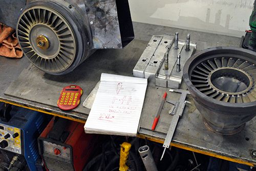 While I had the freepower section removed I wanted to see how the internals of the gearbox was holding together, so I removed the C20 turbine wheel and found this: 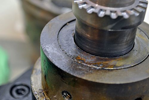 Hmm, must be oil from the bearing lubrication that has overheated. That might be the cause for the slight rubbing I could feel when turning the input shaft, it called for further investigation. 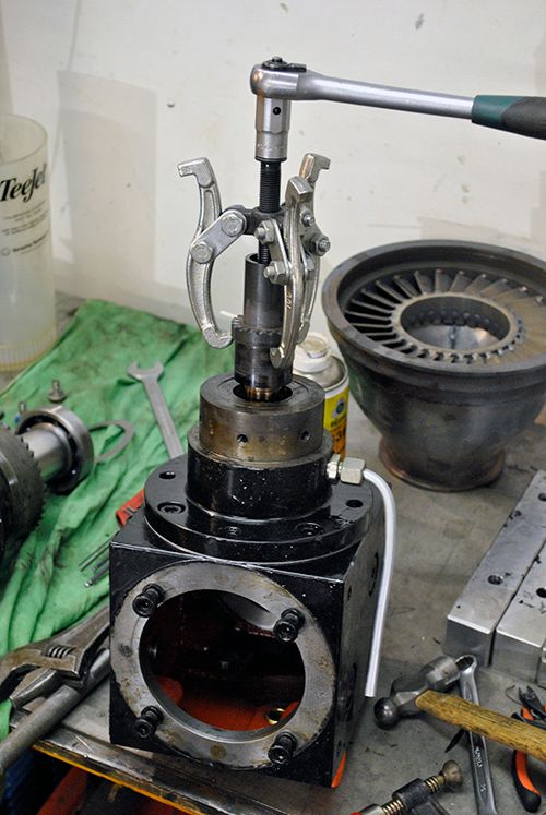 It wasn´t hard to spot the problem, the composite cage for the front hybrid bearing had melted as you can clearly see in the pic below. Good thing that I decided to check since another run with this bearing could have ended in disaster. 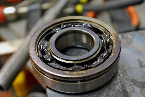 It wasn´t completely unexpected, I had hoped that the bleed air flow through the bearing would keep it cool enough for the cage to survive but that was clearly not the case. Before spending even more money on a full complement ceramic bearing I will try a standard steel C3 bearing and see how well it survives, if I´ll make sure not to overspeed the gearbox perhaps it can endure the stress. Cheers! /Anders |
|
|
|
Post by racket on Jul 27, 2014 18:14:08 GMT -5
Hi Anders
Whats the oil flow rate into the bearing ??
Interesting how the "curvic" lugs on your coupling piece seems to be running cooler than the section closer to the gearbox ,........ is there a chance that the coupling was rubbing something , does it need some cooling air in that region to stop hot exhaust gases heating things up ?
How do the gears look after their run ??
Cheers
John
|
|


