|
|
Post by Johansson on Aug 31, 2014 2:29:50 GMT -5
Hi Ian Well spotted :-) A boundary layer might develop on the flat wall that is eventually "dragged??" into the bellmouth , they can get up to 0.3" thick and can be a problem , a standoff bellmouth wouldn't be able to "pickup" that boundary layer ..........mmmmmmm, interesting thought , a T2 gauge should soon tell us if theres a turbulence problem affecting compression. Cheers John I´ll make sure to add one before the next test.  |
|
ripp
Veteran Member
 I'm sorry, I don't speak english, so I torment you (and myself) with a translation program,Sorry
Joined: January 2013
Posts: 230
|
Post by ripp on Aug 31, 2014 4:45:05 GMT -5
very interesting test data! after suspension of the limitation after the turbine could also help a feeding the compressor wheel inlet    regards Ralph translate.google.at |
|
|
|
Post by Johansson on Aug 31, 2014 7:56:38 GMT -5
Thank you Ralph! I think Google Translate messed up a bit though because I don´t understand what you just wrote. Here is an old log from the test run where my comp nut dropped off, we were manually writing the numbers down but didn´t make it all the way. A few air leaks are sealed since then but the engine is more or less the same. I ran it with a 89mm jet nozzle. 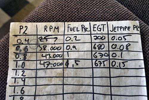 Cheers! /Anders |
|
|
|
Post by racket on Aug 31, 2014 18:22:09 GMT -5
Hi Anders
Mmmm, looks like there wasn't much difference in the jetpipe pressure , but a tad hotter with the jet nozzle , we might need to wait for you to re install the nozzle to cross check .
It was interesting that your recent test run temps reduced a bit once the rpm increased above idle and stayed fairly constant over a very large range of P2s until right up at the top end , it might indicate a slight "off design" diffuser configuration at idle , but OK over a wide mid range and probably even at the top of the rpm range with the temps only rising sharply at the end due to the large increase in jetpipe pressure lowering the pressure drop across the turb stage .
Its really only that idling temp thats a big concern , the mid range is acceptable .
Cheers
John
|
|
|
|
Post by smithy1 on Aug 31, 2014 18:56:14 GMT -5
Hi Anders,
Love your work......
Agree with John here....Those idle/low P2 pressure EGT's are indeed a concern, as John mentions...it'll be interesting to see what results you get with the different jet nozzle and resultant pressures. It is difficult to make a diffuser....and most other flow/pressure dependent parts to a certain degree, which will suit all conditions, what works nicely at one point can be slightly "off" at another.
I'm sure you're well aware...when those temps start getting up into the 800C+ range we start to worry, it means TIT's are approaching the limits of the materials we're using.
Cheers,
Smithy.
|
|
|
|
Post by Johansson on Aug 31, 2014 23:16:21 GMT -5
Could air leaks be causing some of the high idle temps? At the end of the clip when the engine starts smoking a bit (for some reason I´ll figure out) smoke is coming from the seal between the casing and the turbine wheel housing, so there must be some leakage there. With a T2 gauge installed the next test should indicate if the temp issue comes from the cold side or the hot side of the engine, the air box could be causing all sorts of strange flows into the engine and the rev counter diodes aren´t exactly helping either in the position they are sitting. If my memory serves me correct I did get the idling temps down to a point where the engine behaved normally, i.e. low idle temps and rising with increasing P2. Too bad I didn´t have a dashboard camera installed throughout the bench testing, that would have saved me some guessing... My Swedish friend Fläppen has run the numbers now and the only way for him to get the numbers to make sense was to decrease compressor efficiency from an estimated max 81% to 66%, other efficiencies had to be lowered a bit as well. He´ll send me plots of the results as soon as he can, I´ll upload them here when I get them. Blocked syringe needles etc might be another cause, I´ll check that when I take the engine apart for the P2 gauge installation. I poured a cc of kerosine out of the engine casing drain after the run but that was probably the fuel left in the manifold that dribbled out after shutdown. That is a bit of a concern actually, after I shut the engine down I get some flames out of the exhaust which are easy to put out now by blowing cooling air through the engine but not so easily put out 2 km´s away from the race pits after a run. Might have to figure something out later. All part of the wonderful world of R&D! Cheers! /Anders |
|
|
|
Post by racket on Aug 31, 2014 23:38:12 GMT -5
Hi Anders
The post shutdown flames could be fuel dribbling from the fuel manifold as residual heat boils the fuel in the feed line, some commercial engines use compressed air to purge any fuel inside the engine as soon as the fuel is shut off ...............it could also be a bit of oil leakage through the turb seal .
Comp efficiency at idle could be 66% , in which case your T2 will be ~69 deg C at a P2 of 0.5 bar ...........yep, the T2 gauge will soon show up the problem if its at the cold end
Cheers
John
|
|
|
|
Post by Johansson on Sept 1, 2014 2:02:35 GMT -5
Hi Anders The post shutdown flames could be fuel dribbling from the fuel manifold as residual heat boils the fuel in the feed line, some commercial engines use compressed air to purge any fuel inside the engine as soon as the fuel is shut off ...............it could also be a bit of oil leakage through the turb seal . Comp efficiency at idle could be 66% , in which case your T2 will be ~69 deg C at a P2 of 0.5 bar ...........yep, the T2 gauge will soon show up the problem if its at the cold end Cheers John Hi John, I don´t think there is any oil leaking, I´ve been running the oil pump over a minute after shutdown to keep heat soak at bay and not a drop of oil can be found in the casing afterwards. It feels sooooooo damn good after all the trouble I´ve been through with oil leaks on this engine. I´ll search Ebay for a suitable T2 probe, I have the turbine boat engine to work on while waitinig for the probe to arrive. Cheers! /Anders |
|
|
|
Post by unlimitedengine on Sept 1, 2014 9:27:34 GMT -5
Hello I am new here. My English is not good. Your project is very interresting. When i understand right, is the temperatur of exhaust too high. I believe the angle (blade angle) of turbine (exhaut turbine) is too big. What is the wings angle of your exhaust turbine? In model gas turbine is an angle of about 37 degrees good. A angle of 45 degrees increases very the temperature. best regards UnlimitedEngine  |
|
|
|
Post by finiteparts on Sept 1, 2014 12:06:41 GMT -5
Anders, I am looking forward to seeing what you ultimately find to reduce your engine temps and I can't wait to see the video of you really giving it the FULL throttle. I wanted to add a few comments to hopefully help, but I am sure you are getting tired of hearing everybody and his brother telling you his personal opinion on this...so I apologize if this is getting annoying. The first comment concerns the 68% efficiency that your friend had to use to get the numbers to work. I wouldn't think this would be too far from what might be realistic. If we look at the compressor map, 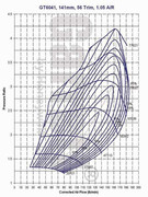 You see that the efficiency lines are pretty closely stacked at the lower pressure ratios AND because you are not using the compressor in its original vaneless diffuser configuration, this map is really not how your compressor system will behave. Vaned diffusers are well documented to narrow the map width due to their reduced ability to handle off-incident airflow at the pick-up region (or what some term the zone of rapid adjustment, where the flow is entering the diffuser vanes, but hasn't reached the throat region). So with a narrowed map width, the efficiency lines will likely be packed in much tighter than the vaneless configuration. If for the sake of arguement, we look at the compressor map at your 1.5 bar reading at around 55 krpm, that roughly (since the rpm are likely corrected values and I haven't calculated the actual rpms) puts you on the map at just under PR=2.5 and assuming the 55 krpm follws a similar trend as the 56392 krpm, there is a large flat area that the engine could be operating at. You could be on either side of peak efficiency island. So, what might help is to incorporate a rough mass flow calculation by measuring the velocity of the air entering the inlet scoop. Incorporating a static and dynamic pressure measurement at the inlet plane, you could calculate a very rough flow velocity and then apply it to the inlet area to get a mass flow value. It will be very rough, but it will tell you roughly were you are operating relative to the original map, which isn't going to be very accurate, but you will have a sense if you are really far out in operating space, plus it will help your calculations. I made one for my old engine out of an air filter snorkel and some small brass tubing. It worked well for getting me in the ball park on the mass flow. Another issue with only reading the turbine exit temperature is that you are speculating on the temperature drop through the turbine. I would suggest adding a thermocouple upstream of the turbine so that you are reading the turbine inlet temperature, the value that you are really interested in. With both a turbine inlet temperature and outlet temp, you could calculate a rough idea of the turbine temp drop and thus the turbine power. I say "rough" because you really need to have a total temp probe and an immersion thermocouple is really only getting static temp values (total temp requires bringing the flow to a full stop without losses (isentropically - no change in entropy)). I know that alot of people get worried about having a t/c upstream of the turbine in case it "burns-off", but if your inlet temperature is limited to 1600 F, the capability of the t/c is well above that...and if you get a thick enough probe, the thermal response time will be low enough that random spikes in gas temperature can be handled quite well. Below is a link to Omega's site, where they sell Inconel 600 sheathed t/cs that are capable up to 2100F...I have been looking at the 1/4 or 3/16th inch ones for my next engine. www.omega.com/pptst/TJ36-XCiB_chb.htmlIf you are worried about an Inconel sheathed t/c melting and going downstream, then you should probably worry more about your turbine wheel. Inconel 713C melts around 2300-2350F, while 718 melts at 2300-2437F and finally, Inconel 600 melts around 2470-2575F. Since your turbine wheel is also subject to high centrifugal loads, the temperature effects would be realized on it well before the t/c failed. If it was me, I would put the t/c just upstream of a NGV, maybe slightly off-centered from it's centerline so that the wake behind the t/c doesn't create a stagnation region that inhibits the flow from fully passing around the t/c. With the larger sized t/c, the thermal response time will be slower, but since you really want to run your measurements at "stable" points, you need to wait anyway to get the operating condition to stabilize. Since there is the requirement for acceleration or deceleration of the engine to be in a unstabilized condition (more or less power in the turbine than is needed by the compressor+mechanical losses), it is by definition that in order to get a stabilized data point, you have to wait for the system to settle. Additionally, I think that the T2 temp sensor will definitely help for diagnostics. Good luck! Chris |
|
|
|
Post by finiteparts on Sept 1, 2014 12:21:17 GMT -5
Here are a few pics of the old snorkel flow meter...pretty simple...the velocities were fairly low, so a decent quality magnehelic differential pressure gauge was needed, but a cheap manometer probably would have worked too. 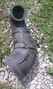 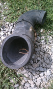 |
|
|
|
Post by finiteparts on Sept 1, 2014 12:38:46 GMT -5
Oh, another thought I had...if you wanted to check the airflow into/or in the vaned diffuser, you might put a heavy oil/thinner grease on the surface so that it will leave streaks after the run of how the airflow at the surface pulled it around. They did this on older turbomachinery development programs to find back-flow issues on diffusers with suspected flow separation conditions.
~ Chris
|
|
|
|
Post by Johansson on Sept 1, 2014 12:55:11 GMT -5
Hello I am new here. My English is not good. Your project is very interresting. When i understand right, is the temperatur of exhaust too high. I believe the angle (blade angle) of turbine (exhaut turbine) is too big. What is the wings angle of your exhaust turbine? In model gas turbine is an angle of about 37 degrees good. A angle of 45 degrees increases very the temperature. best regards UnlimitedEngine View AttachmentHi and welcome to the community! I am running a radial turbine wheel so there is nothing to do about blade angles, John has built several successful engines around the same rotary parts as I am using so the problem lies somewhere else. Cheers! /Anders Anders, I am looking forward to seeing what you ultimately find to reduce your engine temps and I can't wait to see the video of you really giving it the FULL throttle. I wanted to add a few comments to hopefully help, but I am sure you are getting tired of hearing everybody and his brother telling you his personal opinion on this...so I apologize if this is getting annoying. The first comment concerns the 68% efficiency that your friend had to use to get the numbers to work. I wouldn't think this would be too far from what might be realistic. If we look at the compressor map,  You see that the efficiency lines are pretty closely stacked at the lower pressure ratios AND because you are not using the compressor in its original vaneless diffuser configuration, this map is really not how your compressor system will behave. Vaned diffusers are well documented to narrow the map width due to their reduced ability to handle off-incident airflow at the pick-up region (or what some term the zone of rapid adjustment, where the flow is entering the diffuser vanes, but hasn't reached the throat region). So with a narrowed map width, the efficiency lines will likely be packed in much tighter than the vaneless configuration. If for the sake of arguement, we look at the compressor map at your 1.5 bar reading at around 55 krpm, that roughly (since the rpm are likely corrected values and I haven't calculated the actual rpms) puts you on the map at just under PR=2.5 and assuming the 55 krpm follws a similar trend as the 56392 krpm, there is a large flat area that the engine could be operating at. You could be on either side of peak efficiency island. So, what might help is to incorporate a rough mass flow calculation by measuring the velocity of the air entering the inlet scoop. Incorporating a static and dynamic pressure measurement at the inlet plane, you could calculate a very rough flow velocity and then apply it to the inlet area to get a mass flow value. It will be very rough, but it will tell you roughly were you are operating relative to the original map, which isn't going to be very accurate, but you will have a sense if you are really far out in operating space, plus it will help your calculations. I made one for my old engine out of an air filter snorkel and some small brass tubing. It worked well for getting me in the ball park on the mass flow. Another issue with only reading the turbine exit temperature is that you are speculating on the temperature drop through the turbine. I would suggest adding a thermocouple upstream of the turbine so that you are reading the turbine inlet temperature, the value that you are really interested in. With both a turbine inlet temperature and outlet temp, you could calculate a rough idea of the turbine temp drop and thus the turbine power. I say "rough" because you really need to have a total temp probe and an immersion thermocouple is really only getting static temp values (total temp requires bringing the flow to a full stop without losses (isentropically - no change in entropy)). I know that alot of people get worried about having a t/c upstream of the turbine in case it "burns-off", but if your inlet temperature is limited to 1600 F, the capability of the t/c is well above that...and if you get a thick enough probe, the thermal response time will be low enough that random spikes in gas temperature can be handled quite well. Below is a link to Omega's site, where they sell Inconel 600 sheathed t/cs that are capable up to 2100F...I have been looking at the 1/4 or 3/16th inch ones for my next engine. www.omega.com/pptst/TJ36-XCiB_chb.htmlIf you are worried about an Inconel sheathed t/c melting and going downstream, then you should probably worry more about your turbine wheel. Inconel 713C melts around 2300-2350F, while 718 melts at 2300-2437F and finally, Inconel 600 melts around 2470-2575F. Since your turbine wheel is also subject to high centrifugal loads, the temperature effects would be realized on it well before the t/c failed. If it was me, I would put the t/c just upstream of a NGV, maybe slightly off-centered from it's centerline so that the wake behind the t/c doesn't create a stagnation region that inhibits the flow from fully passing around the t/c. With the larger sized t/c, the thermal response time will be slower, but since you really want to run your measurements at "stable" points, you need to wait anyway to get the operating condition to stabilize. Since there is the requirement for acceleration or deceleration of the engine to be in a unstabilized condition (more or less power in the turbine than is needed by the compressor+mechanical losses), it is by definition that in order to get a stabilized data point, you have to wait for the system to settle. Additionally, I think that the T2 temp sensor will definitely help for diagnostics. Good luck! Chris Hi Chris! I am NOT in any way getting bored by your comments, reading your thoughts about this is like the time I found a well worn porn magazine in the big kids tree house when I was 8. Measuring inlet velocity you say, would it really be possible to use a pitot tube when air is sucked past it? It feels like I would need some ram air for that to work. I have a static P1 gauge fitted already but the scale is a bit too rough to collect any useful data from it. I might borrow a digital gauge from work which is much finer in scale. Adding a TIT probe is no big deal, I can do that before running the engine again. John and everyone else, if the NGV area is on the large side wouldn´t it be possible to blank off one of the NGV slots by welding a stainless sheet between two of the vane inlets? I´d rather try some tricks on this one than having to build a completely new one without knowing if it would solve anything. Cheers! /Anders |
|
|
|
Post by Johansson on Sept 1, 2014 12:57:27 GMT -5
Oh, another thought I had...if you wanted to check the airflow into/or in the vaned diffuser, you might put a heavy oil/thinner grease on the surface so that it will leave streaks after the run of how the airflow at the surface pulled it around. They did this on older turbomachinery development programs to find back-flow issues on diffusers with suspected flow separation conditions. ~ Chris Hi Chris, That would work, but it would require a complete engine teardown between every test run. I´ll try it if everything else fails though, thanks for the idea. Cheers! /Anders Edit: You got the wrong compressor map, here is the TV94 map: 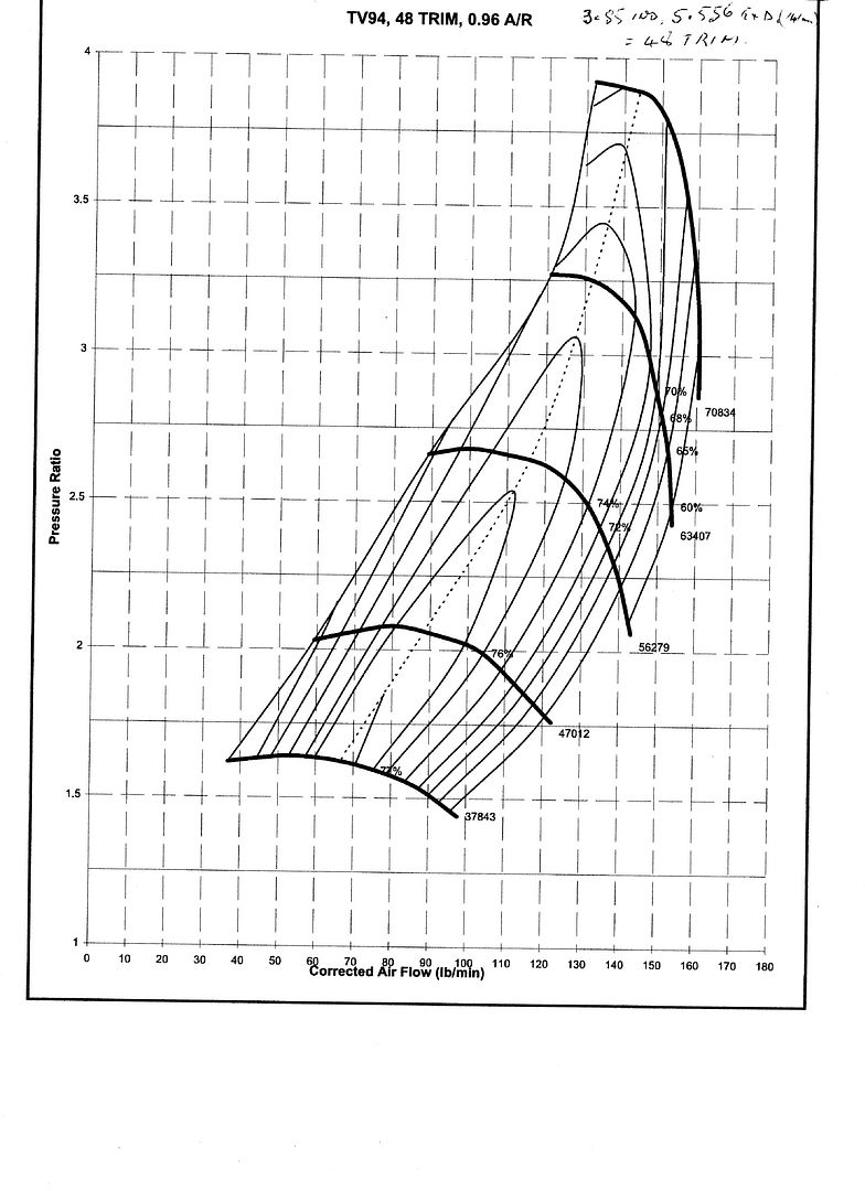 |
|
|
|
Post by finiteparts on Sept 1, 2014 14:12:58 GMT -5
Anders,
Yes, you can measure the flow even if it is being sucked past the pitot tube. You are just measuring the difference between the two pressures (static and total, I incorrectly stated above that you are measuring the dynamic pressure, which is only partially true, you are really measuring the TOTAL pressure which is made up of the static and dynamic components), so it doesn't matter how the flow is being caused to pass by the measurement plane. But, you will want to measure the two different components very close to each other. If you measure them at different locations, you are not getting an accurate value since the flow field could be imposing different static pressures on different areas of the flow. With the static and total pressures taken in the same vicinity, you have simply to back out the pressure rise due to the dynamic pressure...and thus the velocity. There might be a slight error due to the reduced density at the inlet, but I would think you are far enough from the inlet that it should be small...if it is not small, you might have too small of an inlet. You could also adjust the inlet density by using the ideal gas law, P=R*density*T or rearranged to give, density = P/(RT).
You should be slow enough (under M=0.3) that the compressibility effects are negligible, so using the incompressible equation gives:
total pressure = Pstatic + Pdynamic = Pstatic + 1/2(density*V^2)
solving for the mean flow velocity gives,
V = SQRT((2/density)*(Ptotal - Pstatic))
make sure to check your units and that they work out to m/s of ft/s which ever you are using.
Remember, this is a rough estimate on mass flow since the flow across the inlet plane is almost assuredly not constant. So you are getting a representative velocity from wherever you measure your pressures and then applying that velocity over the entire inlet flow plane. So I would recommend to center the static and total pressure tubes in the inlet plane.
Does that answer your concern?
~ Chris
|
|


