|
|
Post by finiteparts on Nov 13, 2016 21:02:56 GMT -5
Yep....having a already drilled speed sensor port is another bonus! I have a speed sensor from another turbo that will complete this nicely when testing.
~ Chris
|
|
|
|
Post by finiteparts on Nov 13, 2016 21:57:32 GMT -5
In my previous post I mentioned that I had ran some CFD models to look at the distortion produced at the tertiary dilution plane due to the location of the compressor discharge attachment to the combustor. As with any CFD, the model is only as good as the assumptions and data used to generate the model...so I must mention that these runs assume only the cold flow, there is no combustion reaction simulated in these. All of them were run assuming a 5% pressure drop across the combustor system with a 210 F and 45 psia inlet temperature and pressure. I used the standard k-epsilon turbulence approximation set to a "medium" level of inlet turbulence and a scalable wall function. This should get us really close, but with any CFD, it is only an approximation and nothing can be stated as "certain". The combustor was a single can style with the inlet coming in from the side of the can (no tangential entry). What we will be looking at are the velocities in the centerline plane of the tertiary dilution holes. For the first pass, I thought it might be interesting to see how bad it would be if the inlet aligned with the dilution holes. 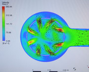 As can be seen, the large dynamic head helps to push the flow into the first two holes. It is hard to see here, but the four holes on the side exhibit reduced flow due to the velocity of the flow around the liner reducing the static pressure and the fact that the flow momentum has a hard time turning 90 degrees into the dilution hole. The back holes flow better due to the reduced flow at the back of the combustor causing an increase in static pressure to drive the flow across the liner. I will note that it is a bit tough to see all this in a 2-d slice, when it is the 3-D flow that is driving these differences. For the next step, I raise the compressor supply tube up so that it impinged on the combustor halfway between the dilution rows as shown here, 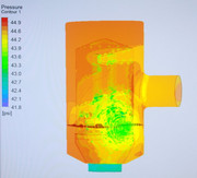 This marginally helped, but the flow on the inlet side is still larger. (The flow is coming in from the same 3 o'clock location as the previous image). The line of sight effect on the first two middle holes, were the dynamic head is overpowering the flow into the holes, greatly reducing their ability to penetrate into the core flow. 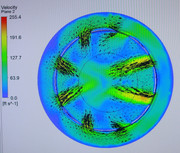 The next step was to increase the annulus flow area as shown here, 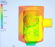 With the larger area to slow the bulk flow within the outer annular space, it can be seen that the jet penetration is much more even, but there is still a momentum effect visible due to the single side entry. 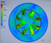 So to try to reduce this side effect, the inlet was moved to the top and a diffuser like entry was added as shown here, 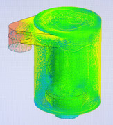 Interestingly, this actually hurt the flow all the way down at the dilution plane. The primary reason was that the flow crossed over the combustor liner top and ran down the backside. The higher flow velocity on the backside of the liner reduced the local static pressure and thus reduced the jet penetration depth. It can also be seen that the momentum effect on the flow through the holes has shifted orientation.  Thinking that a larger headend region might help to diffuse the incoming flow and reduce the flow velocity down the back side of the liner, the headend region was increased as can be seen here; 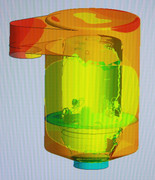 Again, the flow shot over the top of the liner and down the backside of the liner. The increased headend volume did not make a significant impact to correcting the annulus flow distortion. 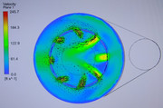 As a final change, the headend flow was forced to go through a set of metering holes arranged circumferentially around the casing.  This approach worked well to supply the outer annulus with an even and fairly undistorted flow field. The reduced penetration depth of the dilution jets is due to the fact that a portion of the combustor systems pressure drop is being used to cross the metering plate and thus the static pressure head available locally at the dilution plane is weaker. 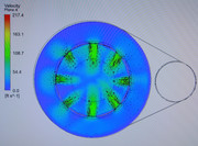 After working through this exercise, I decided to switch the type of fuel introduction method from a vaporizer tube to a prefilming airblast due to its ability to create a stronger primary zone vortex for flame anchoring. I will share that at a later time...perhaps after I run it. Enjoy, Chris |
|
|
|
Post by racket on Nov 13, 2016 23:43:16 GMT -5
|
|
ripcrow
Veteran Member

Joined: December 2015
Posts: 114 
|
Post by ripcrow on Dec 24, 2016 23:01:44 GMT -5
Is this a better design  |
|
|
|
Post by finiteparts on Dec 27, 2016 18:12:51 GMT -5
Hey ripcrow,
I see from the other post that you were trying to "straighten" the flow path for the air to the combustor, which is a good way to reduce losses due to flow turning, but I am not sure that this combustor offers any advantages. The fact is that you are still turning the flow a full 180 degrees in the path from the compressor discharge to the turbine inlet.
As John mentioned, with the flows at low speeds, the flow losses are reduced...but, that being said, doing anything that you can to reduce flow losses ultimately helps your engine to operate better.
Unfortunately, there are other variables that the design impacts. The first thing that strikes me is the expanding annulus cross-sectional area as the flow goes toward the dilution zone. This could cause problems since the flow is diffusing and the mass flow is being reduced as the other zones pull off what they need. This could lead to a very slow, unstable flow that may produce a distorted dilution feed.
The second thing that strikes me is that you will likely begin to accelerate the flow while the reaction is still progressing. This might lead to a higher fundamental pressure loss (due to heat addition in a confined volume) and thus a larger hit to the overall cycle efficiency. This one really is dependent on the how the reaction is anchored in the combustor and the residence time of the reactants.
Thirdly, the compressor discharge flow seems to dump into the combustion casing at a very acute angle...while you are reducing the turning losses in the supply tube, you might get more as the airflow dumps into the casing and flows around the liner.
But, the most important thing to remember about combustor design is that there are a lot of unknown variables and sometimes it is just worth trying...so sometimes the best way to test a theory is just to build it and test it.
Good luck!
Chris
|
|
|
|
Post by finiteparts on Jul 18, 2018 20:27:59 GMT -5
So I finally scored one of the axial turbine stages from the Detroit DD15 turbocompounded engines. They appear to have come down in cost recently and there are several at relatively decent prices on flea-bay.  This thing is big....larger than I had expected.  I will try to measure the tip clearance if I get some time this weekend....they appear to have a relatively thick chord...I will measure that when I take it apart.  The turbine O.D. measures roughly 5.25 inches...  The hub diameter measures roughly 3.375 inches...  Even thought the housing is a cast part, it looks to be very well designed from an aerodynamic sense to guide the flow out of the housing effectively. Once I clean the oil off the inside of this housing, I will get a better shot of the surface finish.  Once I get it apart, I will measure up the turbine and NGV throat areas. I may use Repro-mold to get a more accurate measurement. Stay tuned! Chris |
|
|
|
Post by enginewhisperer on Jul 18, 2018 21:42:05 GMT -5
very interesting!
I had tried to buy one previously but the size and weight info the seller told me seemed way overkill, and I wouldn't be able to transport it so I gave up for now.
Did you weigh it?
|
|
|
|
Post by enginewhisperer on Jul 18, 2018 21:46:21 GMT -5
|
|
|
|
Post by racket on Jul 18, 2018 22:34:09 GMT -5
I think they need the "fluid coupling" to prevent crankshaft "vibration??" from feeding back to the relatively more fragile freepower gearing
|
|
|
|
Post by enginewhisperer on Jul 18, 2018 23:06:29 GMT -5
yeah they would definitely need some sort of flexible coupling / damper. Maybe it's not a real torque converter, but I could imagine a torque converter giving some benefit in that application.
|
|
|
|
Post by finiteparts on Jul 19, 2018 22:10:06 GMT -5
No, I haven't weighed it, but I can try to do that over the weekend if I can get some free time.
And yes, it does have a small torque converter (so called "hydrodynamic clutch") to fluidicly couple the two separate sides of the torque path. As John mentioned, if they were mechanically coupled, the transmission of the crankshaft torsional vibrations would be amplified by the relative increase in gear ratio to a very destructive level at the turbine side of the torque path (it's around 30:1 reduction from the turbine, at up to 60,000 rpm to the crankshaft at around 2000 rpm). It also allows the turbine to run closer to where its speed wants to be and then the torque is transferred through the converter to the speed that the gear train is seeing from the crank. If this was not the case, you would have to speed match the turbine wheel to the crank, which would not work well at all.
Additionally, there is a "freewheel" device (likely an over-running clutch) that decouples the torque converter from the turbine when the engine is operating at part loads, so that the turbine is not being driven by the crankshaft and robbing power. This can be thought of a a one way check valve for crankshaft power...it only allows the turbine to put in power to the crankshaft.
It is a very interesting system.
- Chris
|
|
brayton
New Member
Joined: July 2018
Posts: 9
|
Post by brayton on Jul 29, 2018 0:49:19 GMT -5
Hello Chris, I would assume that you or some of the members here are aware of the development of this small turboshaft / turboprop engine? www.underfunded.com/ProjectofTheMonth/jet.php The current owner, Jason, has it listed on E bay. I got a chance to view it recently and it's really a fine piece of work. He has nearly enough parts to make 2 complete engines. Unfortunately it looks like it never got past the testing stage. The engine is rated at 100 hp, weighs 40 lbs and produced 460 lbs thrust. Here's the e bay link www.ebay.com/itm/100hp-MTE-TURBOPROP-gas-turbine-jet-engine-VTOL-experimental-aircraft-helicopter/223047364600 and some video of it running along with some description and specs. www.youtube.com/watch?v=cRfuMvBwMxQ I believe the weak link may have been the fuel consumption @ 100 lbs / hr at full load. Maybe gearbox wear / longevity was also a concern? With regards to turbo compounding I believe Scania was the first to re introduce the concept in the early 2000's but they have since abandon it. The next was Detroit with the DD16 in about 2010?. and now Volvo is also in the turbo compound game. I'm not aware of Cummins, or CAT ever offering a turbo compound model. Maybe there's an easy way to eliminate the fluid coupling from the gearbox to reduce the complexity and weight? If so that seems like a pretty attractive proven power turbine option. I'm interested in learning more about the possible adaptation of the turbo compound / gear reduction components to a power turbine application.  |
|
|
|
Post by racket on Jul 29, 2018 2:40:38 GMT -5
Hi John
Yep , saw it on Ebay ..............but expensive :-(
Nice bit of kit though .
Cheers
John
|
|
brayton
New Member
Joined: July 2018
Posts: 9
|
Post by brayton on Jul 30, 2018 1:30:38 GMT -5
|
|
|
|
Post by racket on Jul 30, 2018 4:22:44 GMT -5
Hi John
Nope , thats a new one .
Their specs are a bit dodgy , they're trying to tell us the engine is flat rated to 33,000 ft , heh heh , must be the only one in the world , static pressure at 33,000 is only 3.8 psia or ~25% of sea level, they ain't gunna turn out sea level power .
The second concern is fuel burn rate , 27 kgs- 59.4 lbs of diesel for 100 hp , thats <0.6 lbs/hp/hr , using only a 3.5 PR , the Allison C20 heli engine running twice that PR has ~0.65 lb/hp/hr , now the laws of thermodynamics seem to be getting stretched here .
Sounds all a bit too good to be true :-(
But nice looking engines :-)
Cheers
John
|
|


