|
|
Post by smithy1 on Jun 1, 2015 17:54:38 GMT -5
Hi Smithy Heh heh , 23,000 rpm , you've certainly got her tuned nicely :-) 680C at 35 psi and full noise ............nice. Yep , time to "explore" 40 plus ;-) Video please . Yes, your cuppa is waiting . Cheers John Thanks mate......I didn't take any video  ....although Marc was there on the day, I'm unsure if he was present or took any video of the "beast" running.... Video doesn't really do it justice though...After the runs I had many an onlooker tell me I was "re-arranging their organs" with the A/B hits...  Doh...I've done it again....hi-jacking someone else's thread again...Sorry.  Cheers, Smithy. |
|
|
|
Post by racket on Jun 1, 2015 18:52:49 GMT -5
Hi Smithy
LOL, "organ re-arrangement" , yep, an apt description of the forces involved.............yeh, video doesn't produce the "feel"
A tad more P2 and those TOTs will be right where you want them at ~720-740 C ( 900 C for the T I T ) , though they could go another 100 C higher with relative safety for a short period ;-)
Heh heh , get back to your own thread and tell me about the A/B fueling as it is now ...........you know I love specs :-)
Cheers
John
|
|
turbomarc
Junior Member

Joined: May 2015
Posts: 56 
|
Post by turbomarc on Jun 1, 2015 20:51:31 GMT -5
Nah smithy I wasn't around, as I said I would have liked to stay, but I had to take off about five minutes after speaking with you.
Yes, fuel rail and nozzle removal are the first two jobs, tho while I have the flame tube out I might as well try and get rid of the gap between the combustion chamber and the end of the flame tube.
|
|
|
|
Post by finiteparts on Jun 1, 2015 21:28:06 GMT -5
Hi Marc, Thanks for putting up the pictures and sharing your build. I also love the connecting rods as supports! Awesome! I just wanted to clear up something you said, so that you don't go down the wrong path. "Could the extra air bypassing the flame tube be a reason for it running lean thus creating higher temperatures?" It is a common misconception that lean mixtures burn hotter...that is false. Peak flame temperatures occur at a slightly rich condition as shown below: 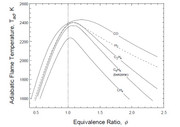
The reason for this is the fact that at high temperatures, the vibrations of certain molecules becomes so vigorous that the molecules break up (process is call dissociation). So at high temperatures, the ideal mixture of oxidizer and fuel (stoichiometric condition) that should produce the highest flame temperature doesn't, because part of that energy is absorbed by breaking bond energies. This changes the heat capacity of the gas (heat capacity is essentially how the molecules vibrate, translate or rotate to "store" the thermal (kinetic) energy). In a simplified sense, this change leads to the shift in the peak adiabatic flame temperature (there are many other factors, to learn more look up dissociation in combustion or in adiabatic flame temperatures). Now everybody that has worked on an IC engine knows, when you get an engine lean, you get a hotter engine. So what gives? The primary issue is that the reaction rate is also a function of the equivalence ratio. The reaction rate peaks at stoichiometric and reduces as you lean or richen the mixture. The reaction time for a lean mixture thus has to increase and the added "burn" time means that the average temperature in the cylinder increases (average temperature over the complete stroke), thus increasing the metal temperatures that are in contact with the flame. The added heat transfer due to the slower process also reduces the thermal efficiency. If you get really far lean, you get lean misfires and detonations that occur at the wrong part of the stroke and cause all kinds of havoc. This isn't such an issue on the rich side, since there is additional fuel to absorb the heat as opposed to it going out the metal walls. Let's switch gears to gas turbines. What we want to do is to burn the fuel in the primary zone at stoichiometric conditions, so you size the primary air holes such that at your design point, you are flowing enough air and fuel that you have the ideal mixture ratio. Because mixing and reactions can't be perfect, you will likely have some incomplete combustion. Incomplete combustion means that you have high carbon monoxide levels (CO), so we pour some more air in through the secondary air holes to burn out the CO to CO2...(note: CO is shown as a fuel in the above figure, which was sort of surprising to me when I first saw it...the reaction is CO + O2 ---> CO2). So now we have burned out the CO and have complete combustion (high CO2)...but the adiabatic flame temperature of kerosene is 3800 F. That can't be good for a Inconel 718C wheel that melts at around 2300-2400 F. So we dilute the combustion products with more air through the tertiary (means - third in order) so that we cool it down to below 1600 F or there abouts , keeping the engine from spewing out some high nickel emissions. It should be apparent why the combustion needs to be completed before the tertiary holes are reached. If the combustion reaction is still trying to occur when the gas flows by the tertiary holes, the "cold" air can in the worst case, freeze the reaction, so that you exhaust incomplete combustion products (high CO and unburned hydrocarbons (HC)). In a not so severe case, you can slow the reaction such that you continue to "burn" in the turbine stage causing overheating of the hot gas path components. Your combustor is likely overheating due to exactly what John said...your fuel is likely just seeping out of you injector and not mixing well...creating a hot streak. If you are bypassing air at the turbine end of the combustor can, you would be running the head-end of the combustor "rich", since the bypass air is short circuiting the combustion process all together. Also, since the bypass gap is essentially a short circuit for the airpath's static pressure, you will have less pressure drop to push the metered air (primary, secondary and tertiary air) and thus get less mixing. I hope that helps to make things more clear on the hot condition of your engine. Good luck! Chris |
|
turbomarc
Junior Member
Joined: May 2015
Posts: 56
|
Post by turbomarc on Jun 2, 2015 5:08:15 GMT -5
Wow, thanks for clearing that up for me finiteparts, yes I am more accustomed to a IC engine. I got home a bit early today, got some time to pull it apart and survey the inside of the combustion chamber, i'm a complete rookie, but i know when things aren't right. Appears as if i had some flames out of three primary holes, in one particular area.  As mentioned earlier, can clearly see why copper wasn't the best choice, tho after having higher than average temp, and the occasional green flame, it's in better condition than i was expecting.  On the inside of the combustion chamber, mixed feelings, was expecting to see heat colouration, just wasn't expecting to see it where it is.  Made me start questioning had i lined the flame tube up right, was it off centre, but i ruled that out.  Also, one issue that Smithy diagnosed on the weekend, was the fuel rail and where the holes are positioned, he mentioned that for best results, same as someone else mentioned earlier in this thread use some pipe with a nut on the end with 6x1mm holes, one on each face of the nut to give the 60 degree separation for a even distribution of gas. I used some of my finest mspaint skills to illustrate roughly what i think should be the new fuel rail, any advice would be welcomed.  So plan of attack is to just change the fuel rail, and remove the jet nozzle restriction, see if that helps bring the temps down abit. Cheers, Marc. |
|
|
|
Post by smithy1 on Jun 2, 2015 17:12:56 GMT -5
Hi Marc,
Good to see your onto it....for the fuel injector, many people just use a long bolt with a hole drilled down from the threaded end through the center for the fuel inlet, but not right through the head end, maybe 1-2mm short of right through, then drill your 1.0mm holes from each hex face so they meet the center hole. Personally I'd start with slightly smaller hole in the hex, maybe 0.7mm, you can always easily make them larger if required, it's a bit difficult to make them smaller after they've been drilled..! Positioning of the fuel nozzle outlet can also be a bit hit 'n miss, might even pay to make it adjustable via a sliding mount maybe...doing a run and inspecting where the flame front starts and adjusting your setup to suit...just thinking out loud. With your welding skills I'm sure you could easily come up with a solution. I can't weld to save my life...
You could always just make up a few different sized injector units ranging from ~0.5mm up to 1.0mm and experiment a bit....there's no hard and fast rule as each turbine build is slightly different even if they look the same. Smaller holes with higher fuel pressure tends to work well. We eventually would like you to run on liquid fuel such as diesel or kerosene as propane can become a tad expensive and it's a pain to constantly have to fill your propane bottle at the nearest petrol station. 20L of diesel will cost ~$25-@30 and last quite a while with your smallish turbine.
When you get to the point of doing a few runs, I'd be happy to pop over and point or nod at things. I believe Andrew (enginewhisperer) is not too far away as well...maybe we could make an afternoon of it..!
Cheers,
Brett.
|
|
|
|
Post by finiteparts on Jun 2, 2015 19:42:26 GMT -5
Hi Marc,
That soot supports the idea that the gap at the bottom of the combustor liner is too big. You are bypassing air through that gap and the combined area of the gap plus the liner holes is large enough that you are not getting a sufficient pressure drop across the liners.
This is evident from the soot marks at the upper holes. The pressure drop is so low that it is easier for the flow to go out through the primary holes and then travel down to the gap, than it is to travel straight down through the gap at the base of the combustor liner/casing. That is not good.
The low pressure drop also likely limited the amount of air entering the head end so that you were likely burning just downstream of the gap at the base of the liner. This would agree with the hot-spot shown in your picture.
~ Chris
|
|
|
|
Post by enginewhisperer on Jun 2, 2015 20:05:46 GMT -5
I believe Andrew (enginewhisperer) is not too far away as well...maybe we could make an afternoon of it..! I'm keen  Also happy to have a turbine build / test day at my workshop. I have all the usual support equipment as well as metal working tools, etc, and a couple of fire extinguishers It'd be good to bolt together some of my turbine parts too! |
|
|
|
Post by finiteparts on Jun 2, 2015 21:06:10 GMT -5
Hi Marc, I made a quick sketch to show you what I think might help.  First, you want to give the fuel as much time as possible to mix and burn out...so you should move the injector near the top. The primary holes need to be set tangent to what is termed the "magic-circle". It is just a circle that spans half of the tube diameter as shown. This will help create a vortical flow in the combustor head-end that anchors the flame. The primary holes should provide enough area to have the air-fuel ratio at approximately the stoichiometric ratio. The gap between the base of the liner and the combustor casing needs to be closed up. It needs to be a slip fit because the liner will increase in length due to thermal expansion and if it was a solid fit, you might buckle the out casing (since your liner is so thick, it will be the stronger member in the thermal fight). Closing up that gap is key to making sure you have enough pressure drop across the liner to drive the air through the holes and deep into the combustor flow so that you have good mixing. The last thing is the elbow bringing in the flow from the compressor discharge. Because it impinges on the combustor liner, it will preferentially feed some holes due to the variation in the local static pressure at each hole. Since you don't have much space between the liner and the casing, I don't think there is much that we can do about that. This non-symmetric static pressure field that is seen by the various dilution holes is the reason that you had back-flow from some of the holes and not others. The velocity of the flow will be highest at the discharge from the elbow and thus the local static pressure there will be lower. As the flow fills the rest of the annulus around the liner, the flow velocity decreases and the local static pressure increases. So my guess is that the soot stains shown above probably were close to the elbow, such that the static pressure inside the combustor liner was higher than the static pressure of the airflow around the liner near the elbow, since the airflow velocity was still high there...sucking the flame out of the liner. I think that if you get that gap closed up, it will increase the pressure differential across the liner and thus keep the flow through the holes going in the correct direction. Good luck! Chris |
|
|
|
Post by smithy1 on Jun 2, 2015 21:15:18 GMT -5
I believe Andrew (enginewhisperer) is not too far away as well...maybe we could make an afternoon of it..! I'm keen Also happy to have a turbine build / test day at my workshop. I have all the usual support equipment as well as metal working tools, etc, and a couple of fire extinguishers It'd be good to bolt together some of my turbine parts too! Excellent...a very kind offer from you Andrew, we should organize a day then....we might even be able to convince John to make a bit of a road trip down from up north, he can stay overnight at my place if he likes and is required. Cheers, Smithy. |
|
|
|
Post by smithy1 on Jun 2, 2015 21:22:51 GMT -5
Nice informative drawing Chris....lots of good info in there and should help Marc with his project.
Cheers,
Smithy
|
|
turbomarc
Junior Member
Joined: May 2015
Posts: 56
|
Post by turbomarc on Jun 2, 2015 21:48:40 GMT -5
Hi Marc, Good to see your onto it....for the fuel injector, many people just use a long bolt with a hole drilled down from the threaded end through the center for the fuel inlet, but not right through the head end, maybe 1-2mm short of right through, then drill your 1.0mm holes from each hex face so they meet the center hole. Personally I'd start with slightly smaller hole in the hex, maybe 0.7mm, you can always easily make them larger if required, it's a bit difficult to make them smaller after they've been drilled..! Positioning of the fuel nozzle outlet can also be a bit hit 'n miss, might even pay to make it adjustable via a sliding mount maybe...doing a run and inspecting where the flame front starts and adjusting your setup to suit...just thinking out loud. With your welding skills I'm sure you could easily come up with a solution. I can't weld to save my life... You could always just make up a few different sized injector units ranging from ~0.5mm up to 1.0mm and experiment a bit....there's no hard and fast rule as each turbine build is slightly different even if they look the same. Smaller holes with higher fuel pressure tends to work well. We eventually would like you to run on liquid fuel such as diesel or kerosene as propane can become a tad expensive and it's a pain to constantly have to fill your propane bottle at the nearest petrol station. 20L of diesel will cost ~$25-@30 and last quite a while with your smallish turbine. When you get to the point of doing a few runs, I'd be happy to pop over and point or nod at things. I believe Andrew (enginewhisperer) is not too far away as well...maybe we could make an afternoon of it..! Cheers, Brett. Yeah, that's a good idea for the different sized jetting, as well as an adjustable fuel rail. Going to visit a mates workshop this afternoon, see if i can get my hands on some half inch tube, and chuck it thru the beaver, then i can have a running thread from end to end, then it is just a matter of having one nut inside, and one outside of the flame tube, and then adjust until desired result is achieved. As for jetting, nuts are cheap, isn't hard to grab a handful, put a cap on one end then just swap them over without having to remove the fuel rail each time. But i really can't see me being able to drill less than 1mm, i just don't have the equipment to deal with such precision, i think even with 1mm i will have to be ever so gentle with my hand drill, i doubt my pedestal drill chuck would even grasp a 1mm drill bit. For the time being as you said Smithy, gas is very forgiving, so for now i might just stick with it till i feel happy that i have got it sorted out and then progress into running a liquid fuel. Also diesel is "free" being a truck driver, 20l here and there is nothing in the grand scheme of things, but i also have a mate that has said if i need any Jet A1 he can supply me with a bit. Chris, yeah, i will be addressing that gap while it is all out at this stage, just build up the material on the end of the flame tube, test fit, grind, test and repeat until sorted, but the downside to that is, i'm still left with the domed end of the combustion chamber that will still leave me with that Vena contracta effect. Enginewhisperer, you wouldn't happen to have a sheetmetal roller by any chance would you, after finding out about the Vena contracta effect and how the domed end isn't the best way to funnel air efficiently into the exhaust housing, im considering making a new combustion chamber to suit my current flame tube. Happy to throw cash your way for the effort if it's something you could do. Test day sounds good, i live in Penrith, but work at Thornleigh so im up there six days a week. Thanks for the help thus far to all involved, much appreciated. Cheers, Marc. |
|
turbomarc
Junior Member
Joined: May 2015
Posts: 56
|
Post by turbomarc on Jun 2, 2015 21:56:44 GMT -5
Thanks Chris,
I'll endeavor to see if i can make that idea blend, being its right in the base might make welding a bitch of a job, not impossible, just harder, might also be yet another good reason to make a new chamber from scratch, because one thing that i think could be done better in hindsight is where the air enters, maybe have it on more of an angle to encourage a smoother swirling effect around the flame tube.
Cheers,
Marc.
|
|
|
|
Post by smithy1 on Jun 2, 2015 22:35:22 GMT -5
Hi Marc, Here's a pic of the 6041's flame tube....it's quite elaborate but John just can't help himself..! You'll note the "tapered" lower section where it interfaces with the turbine inlet....it's actually a slip joint to allow for heat expansion etc...works very well indeed.   Cheers, Smithy. |
|
|
|
Post by smithy1 on Jun 2, 2015 22:42:03 GMT -5
Forgot to upload this pic indicating where the inlet air from compressor enters the outer combustion case, quite low down as can be seen here:  Note the P2 pressure sense line adjacent to the upper right mount bolt. Cheers, Smithy. |
|


 ....although Marc was there on the day, I'm unsure if he was present or took any video of the "beast" running....


