|
|
Post by racket on Mar 17, 2016 18:00:03 GMT -5
Hi Anders
That works nice and quickly , a quick squirt of fuel and she'll be alight :-)
Cheers
John
|
|
|
|
Post by Johansson on Mar 20, 2016 17:03:54 GMT -5
Hi John, Actually it doesen´t, I finished the kero plug last night and tested it only to find that the confined space won´t make the fuel vapor light off. I tried it with propane as well and no luck, the plug lights propane instantly in open air but enclosed in the plug housing I guess it can´t get enough air to light off. Back to the drawing table. I drew up a pattern for casting the compressor cover this weekend, a hefty chunk of aluminum but I figured it is better to leave a bit of extra material for machining since large discs tend to warp a bit.  I split the part in two just to make it fit the printer and started printing it in PLA plastic, it estimated 22 hours print time for the first half. 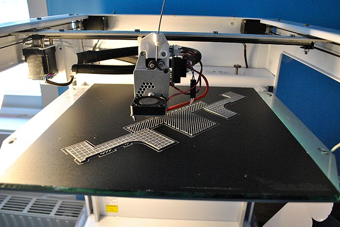 With only an hour or so left the printing temperature started bouncing wildly which ruined the print, bloody shit!  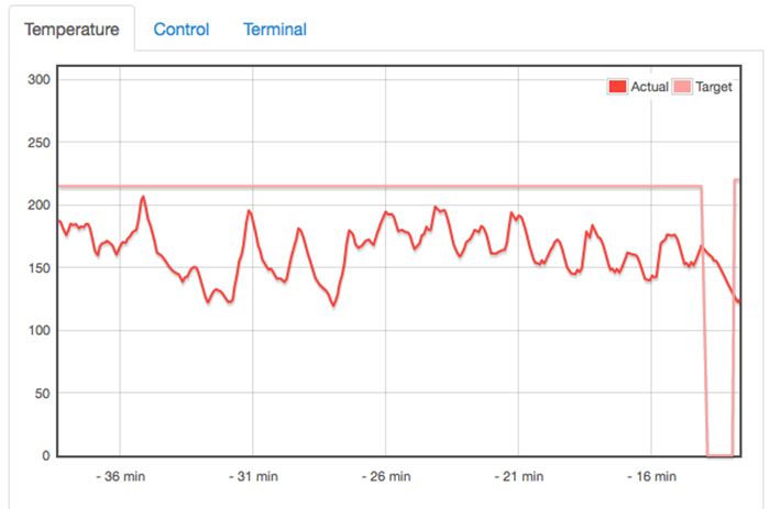 I´ve emailed the manifacturer to find out what the problem can be, it is the third time I have had serious problems with the printer so I am not very happy about it at the moment. Sure it is a fun toy but it is annoying that you can´t trust it to actually work when you need it to.  To make things clear I am not trying to throw shit on this particular brand of 3D printers, I guess every brand has its own problems and I have probably just had bad luck. They have given me quick help the previous times it has failed on me so I hope this will be fixed soon as well. Luckily I have a very skilled and helpful father who will make me a wooden pattern instead, so hopefully I will be able to cast the final aluminum part for JU-02 sometime this spring. Cheers! /Anders |
|
|
|
Post by racket on Mar 21, 2016 3:15:11 GMT -5
Hi Anders
With the igniter maybe it'll work once the engine is being spun over and theres a good blast of air around it .
Bummer about the pattern ................LOL, your father will enjoy having some input ;-)
Cheers
John
|
|
|
|
Post by Johansson on Mar 21, 2016 6:06:56 GMT -5
Hi Anders With the igniter maybe it'll work once the engine is being spun over and theres a good blast of air around it . Bummer about the pattern ................LOL, your father will enjoy having some input ;-) Cheers John Perhaps, but I´ll try to rebuild it so it at least works to atmosphere. Since it has no problem lighting off propane in the open I can still use it as a perfect replacement for the spark ignition in case I don´t want to go the whole kero start route. My father is the real deal, he is the most multi skilled person I have ever met. Too bad he isn´t into the turbine hobby.  |
|
|
|
Post by Johansson on Apr 28, 2016 12:43:51 GMT -5
Bugger, I posted this in the wrong build thread earlier... ________ I decided that the workshop had taken way too much time from the JU-02 project so it was time to put the new lathe to good use. 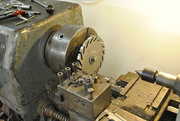 Drilling four M10 holes for the countersunk screws that will hold the NGV to the shaft tunnel. 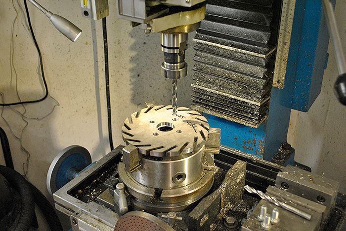 Here I have turned the guide edge that will keep the NGV and shaft tunnel centered. 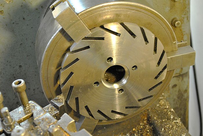 Test fitting time! 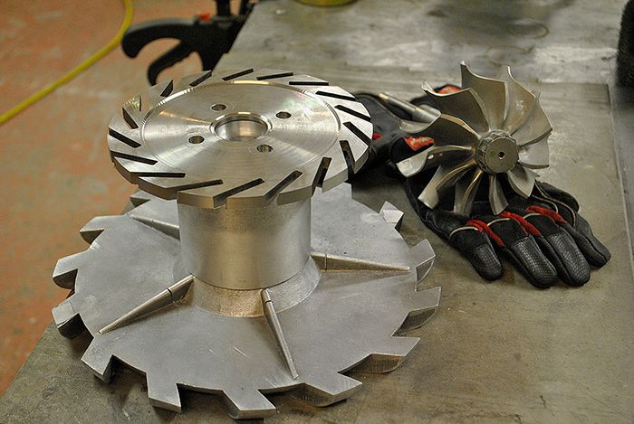 I had to make a small jig to fixate the piston ring seal seat before welding it to the NGV, here I have just finished welding it in place. 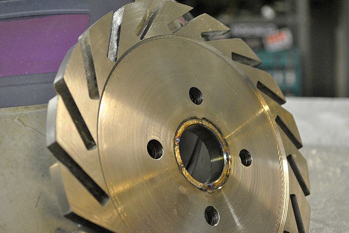 The other side, the reason for the added seat it because the piston ring sits a bit inside the shaft tunnel and I didn´t want to machine it from a 30mm thick NGV plate... 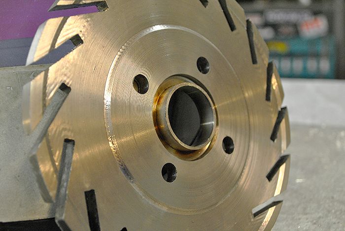 Then I drilled the M10 screw holes in the shaft tunnel so I could fit the two together. 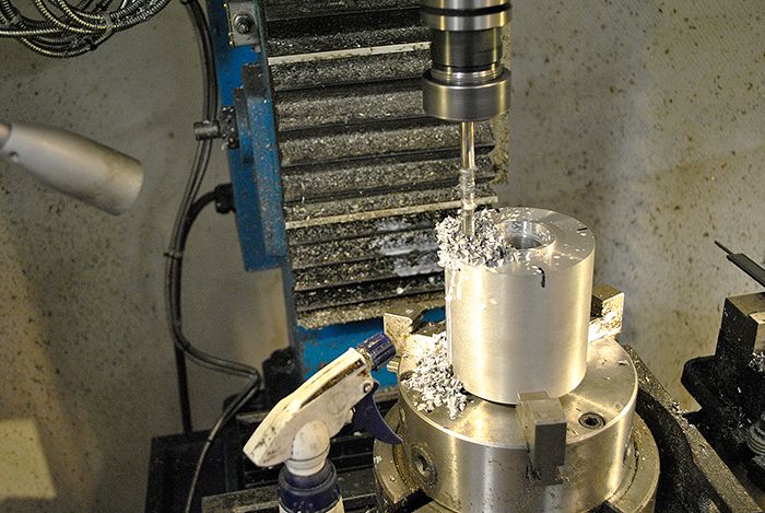 Threading the holes... 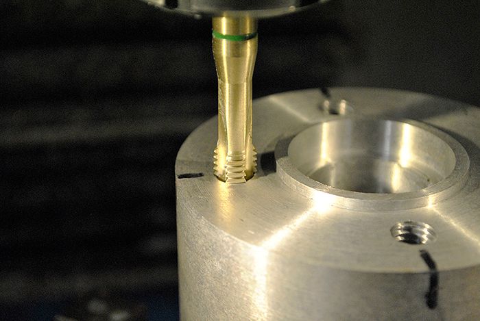 I found a countersink tool that wasn´t at all meant for stainless, but it did the job anyway. Squealed quite a bit though... 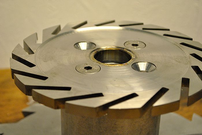 It is slowly starting to resemble a gas turbine engine... 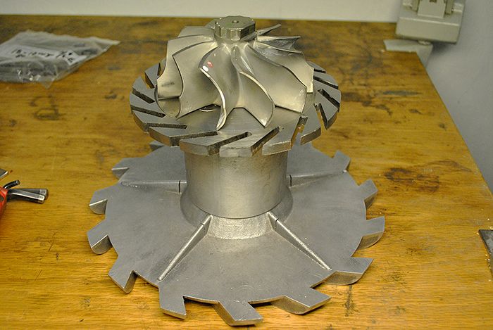 Cheers! /Anders |
|
|
|
Post by Johansson on Apr 29, 2016 18:00:58 GMT -5
After consulting John about the NGV section I figured out a way to make tapered vanes and still get the correct throat width. First I had to make a fixture to get all of the 18 vanes identical, underneath there is a set screw that I use to set the correct angle on the fixture before clamping it in place. 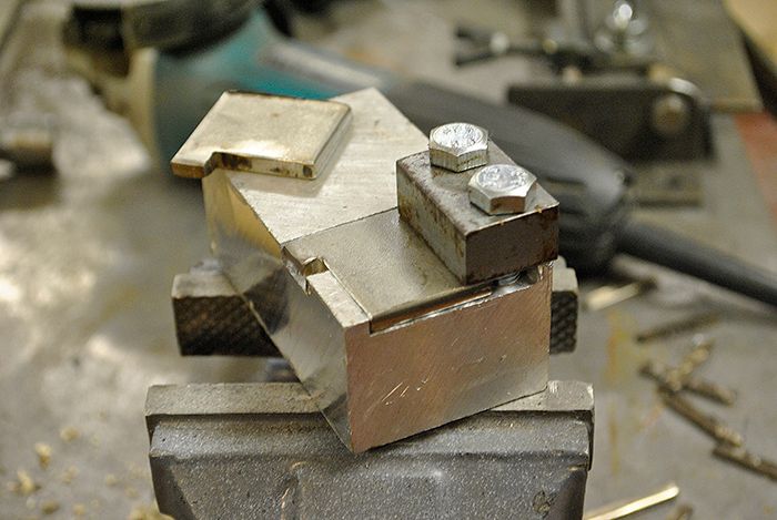 Ready for some milling! 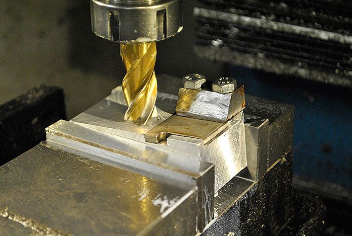 Milling completed! 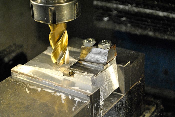 After cleaning the vanes up a bit they looked like this. 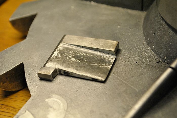 Here are a couple of vanes test fitted in their slots, looks much better than with straight vanes. 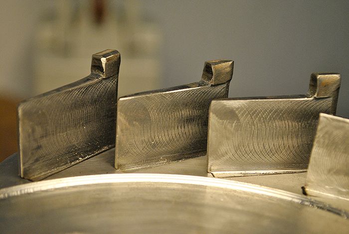 Time for bed, it is way past midnight here. Cheers! /Anders |
|
|
|
Post by madpatty on Apr 29, 2016 19:31:46 GMT -5
Hi Anders,
Was having a look at your NGVs and their fitment inside their slots.
Nice work there sir.
The NGVs can be made removable and replaceable this way.(just a random thought)
As the vanes are held at place by 2 welds(top and bottom side) so one needs to Just remove the shaft tunnel side and Exducer side welds and fit in the new NGV or set of NGVs.
The new NGVs can have separate throat also(so anyone can try and change the throat area also).
I know this sounds weird and your engine will run in its very first design but the idea of removable and replaceable NGVs will be very useful for amateur builders like me or somebody else here.
As i was experiencing a hot spot issue in my engine and NGVs at certain spot were melting away so this method will surely help.
Cheers,
Patty
|
|
ripp
Veteran Member
 I'm sorry, I don't speak english, so I torment you (and myself) with a translation program,Sorry
Joined: January 2013
Posts: 230
|
Post by ripp on Apr 30, 2016 1:22:29 GMT -5
Good idea, so you can adjust the angle ngv and thus improve the running characteristics / performance. Cheers, Ralph translate.google.at  |
|
|
|
Post by pitciblackscotland on Apr 30, 2016 4:17:32 GMT -5
Hi Anders, Nice jig you made up there Was that metal easy to machine up with you mill cutter  Cheers, Mark. |
|
|
|
Post by Johansson on Apr 30, 2016 9:33:13 GMT -5
Unfortunately by adjusting the vane angle you also adjust the throat width, so you would need to modify the slots as well. Most possible to do so a good idea in case I need to modify the engine.
The 253MA was in fact pretty easy to mill, 0.5mm deep cuts and lots of cutting fluid did the trick.
|
|
ripp
Veteran Member
I'm sorry, I don't speak english, so I torment you (and myself) with a translation program,Sorry
Joined: January 2013
Posts: 230
|
Post by ripp on Apr 30, 2016 15:38:25 GMT -5
Hi Anders, what do you mean by "throat width"? John and you used the same turbine wheel and the same ngv, just different angles. The flow through the ngv are the same because all the vanes run to a Point (I think a flat angle, as you use, transmits more power to the turbine wheel). NGV 12-118 Fat Boy   JU-02  Chees, Ralph translate.google.at |
|
|
|
Post by Johansson on Apr 30, 2016 15:53:10 GMT -5
Hi Anders, what do you mean by "throat width"? John and you used the same turbine wheel and the same ngv, just different angles. The flow through the ngv are the same because all the vanes run to a Point (I think a flat angle, as you use, transmits more power to the turbine wheel). Chees, Ralph translate.google.at Hi rip, I mean the width of the narrowest passage through the NGV, if I change the NGV angle that measurement change as well. Imagine pointing the vanes directly at the turbine hub, then the throats will be much larger than if they point at the inducer tips. Cheers! /Anders |
|
|
|
Post by racket on Apr 30, 2016 17:25:46 GMT -5
Hi Ralph
My NGV angle is >30 degrees whilst Anders is closer to 20 degrees .
The best way to get the right angle and its throat width is simply to draw the NGV up on a bit of paper making sure to use the exact shape of the tapered NGV vanes , the actual cut in the NGV wall will be at a slightly different angle to allow for the "tapered" section of the vane being different to the section that goes through the wall, it remains at the original ~3mm .
Yes , Anders "lower" angle will transmit more power to the wheel than my "higher" angle and is one of the reasons I'm having the problems I am with getting my engine to run , but I need the higher angle to get my larger "volume" through the NGV and into the "undersized" turb wheel ..............theres compromises :-(
Cheers
John
|
|
|
|
Post by Johansson on May 1, 2016 13:37:13 GMT -5
The last day alone at home, best get busy then! To keep the heat away from the turbine shaft I drilled four 2.5mm holes that will direct bleed air to the backside of the turbine wheel. 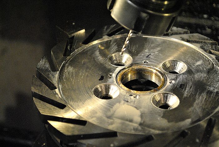 Slots being milled on the surface between NGV and shaft tunnel. 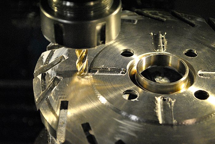 After cleaning the part up a bit it looked like this. 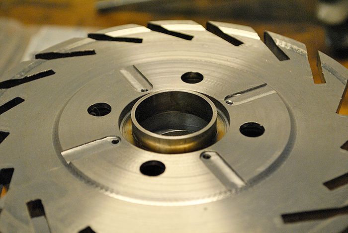 And the turbine side. 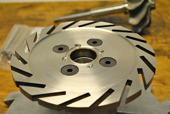 I turned a radius on the NGV entry in the lathe. 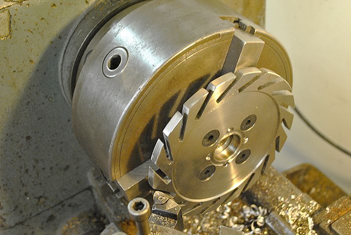 Here the NGV is assembled with the turbine wheel as reference. 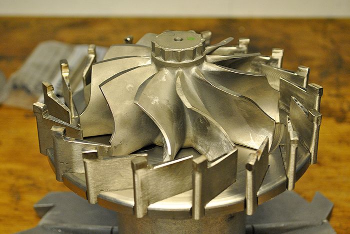 After tapering the vanes the NGV angle got a bit smaller than originally intended, I hope it isn´t too extreme. 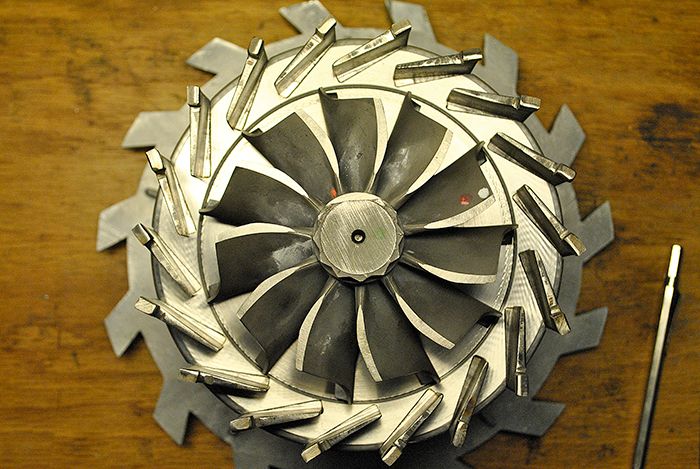 With that done I started on the oil scavenge line in the shaft tunnel, here I am milling the line from between the rear journal bearing and turbine. 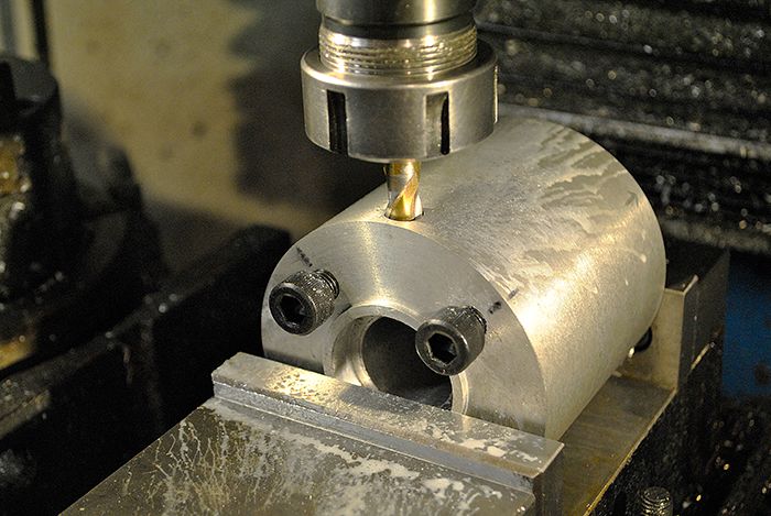 Here I have threaded the end of the hole for an M12 plug, for ease of manufacturing I did it like this instead of drilling an angled hole from the main scavenge port which I haven´t made yet. 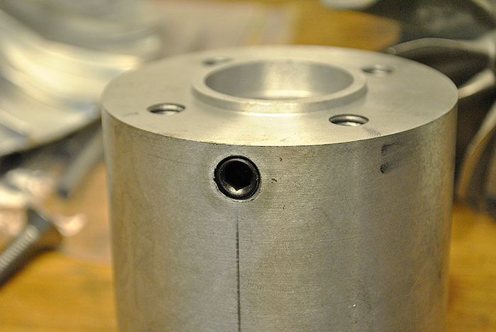 Drilling the main scavenge line. 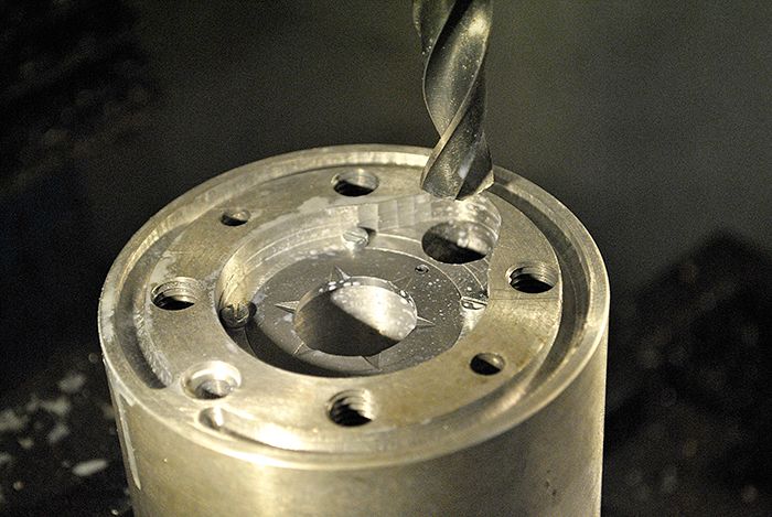 After some porting with the Dremel it looks like this. 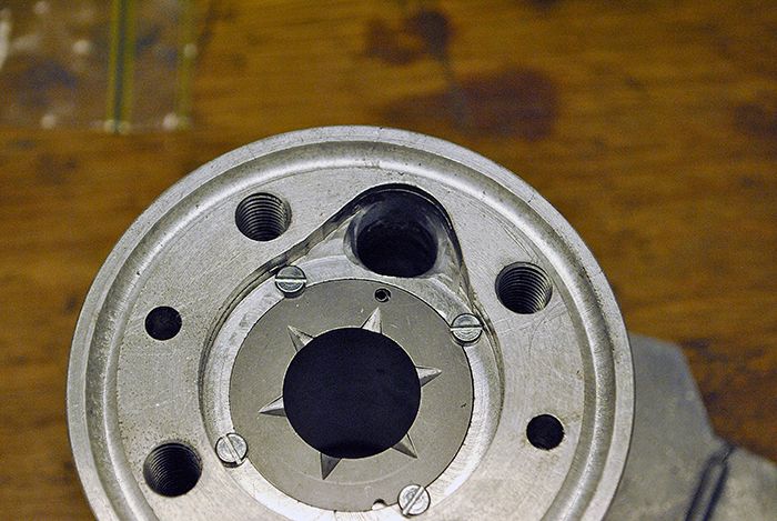 Cheers! /Anders |
|
Chuks
Senior Member
Joined: August 2015
Posts: 497 
|
Post by Chuks on May 3, 2016 13:26:32 GMT -5
Hi Ralph My NGV angle is >30 degrees whilst Anders is closer to 20 degrees . The best way to get the right angle and its throat width is simply to draw the NGV up on a bit of paper making sure to use the exact shape of the tapered NGV vanes , the actual cut in the NGV wall will be at a slightly different angle to allow for the "tapered" section of the vane being different to the section that goes through the wall, it remains at the original ~3mm . Yes , Anders "lower" angle will transmit more power to the wheel than my "higher" angle and is one of the reasons I'm having the problems I am with getting my engine to run , but I need the higher angle to get my larger "volume" through the NGV and into the "undersized" turb wheel ..............theres compromises :-( Cheers John hi John, nice solution for upcomings like me. can you make a rough explanatory drawing as a reference point to further educate me\us?. thanks |
|


