|
|
Post by Johansson on May 3, 2016 16:33:45 GMT -5
After doing the dishes and putting the girls to bed I went out to drill some holes for the studs and evaporator tubes in the NGV outer wall. 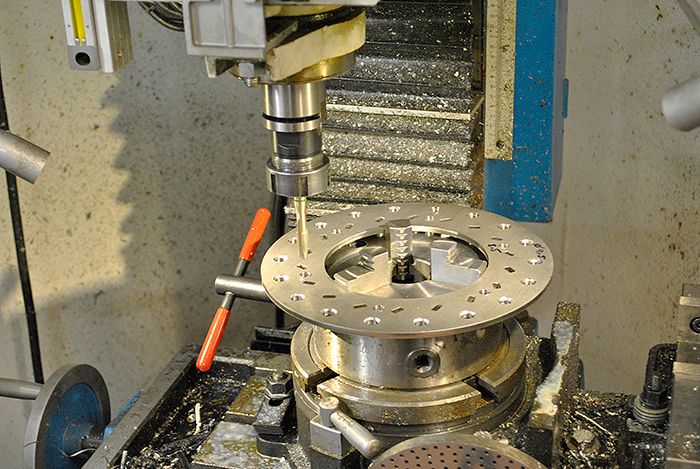 Then I attached the vanes with a couple of small weld dots so I could adjust them for an equal throat width. 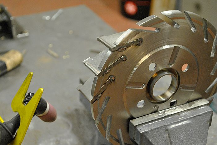 After some light grinding the NGV outer wall slid onto the vanes, there are some final adjustments to the NGV to do before I can weld it together for good. I fitted a pair of evaporator tubes just for reference, they´ll get some D-ing and an inlet flare before welded in place. 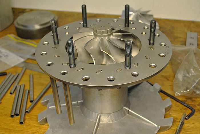 Here you can see the NGV inlet, I´ll turn the inlet section down later to allow the combustor inner liner a sliding fit. 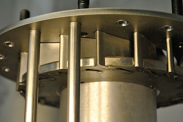 Cheers! /Anders |
|
|
|
Post by racket on May 3, 2016 16:52:27 GMT -5
Hi Anders
She's coming together beautifully :-)
The laser cutting has saved a lot of tedious work, making the NGV assembly is one job I don't look forward to.
Cheers
John
|
|
|
|
Post by Johansson on May 3, 2016 17:02:39 GMT -5
Hi John,
Yeah, having the NGV profiles laser cut really make construction easier. It wasn´t even very expensive, buying a small sheet of 10mm stainless to do it from scratch isn´t exactly for free either...
Cheers!
/Anders
|
|
|
|
Post by Johansson on May 5, 2016 13:29:21 GMT -5
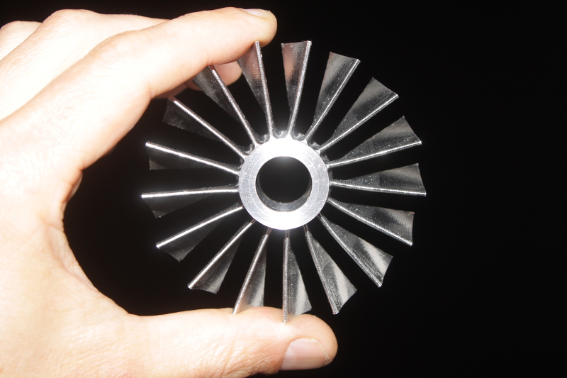
Finally a sunny day that is work free! Besides lots of work around the house and having fun with the family I managed to get a few things done on the JU-02 project. After the final touches to the nozzle guide vanes I welded the NGV outer wall in place. 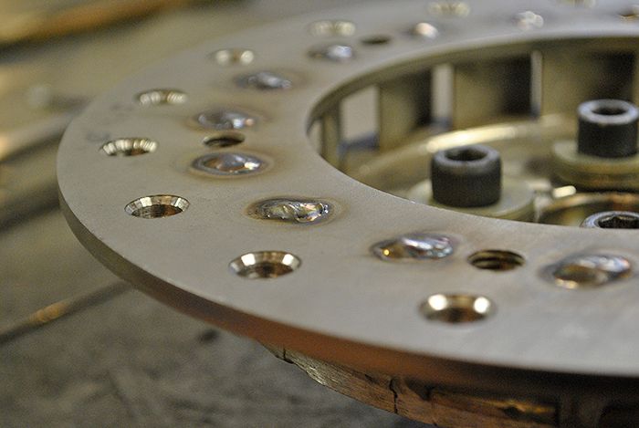 Since welding stainless makes things warp a bit I cleaned the important surfaces off in the lathe. 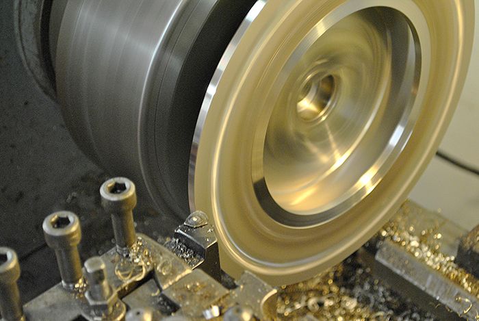 I also made a shelf where the combustor inner liner will rest, since the combustor length will increase with the temps it needs some room to expand freely else it will get damaged. 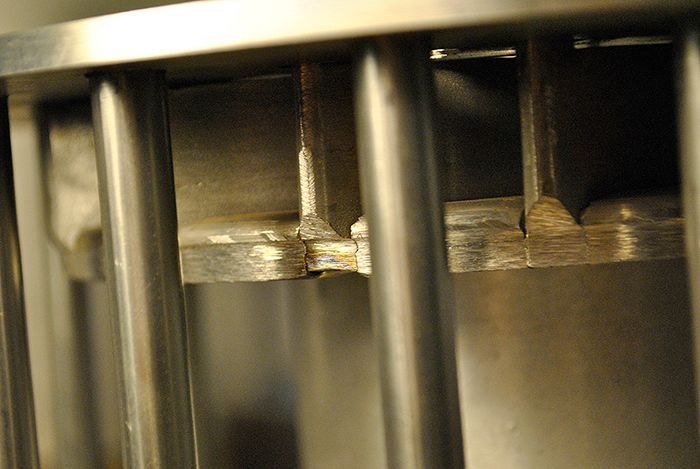 This didn´t turn out bad at all!  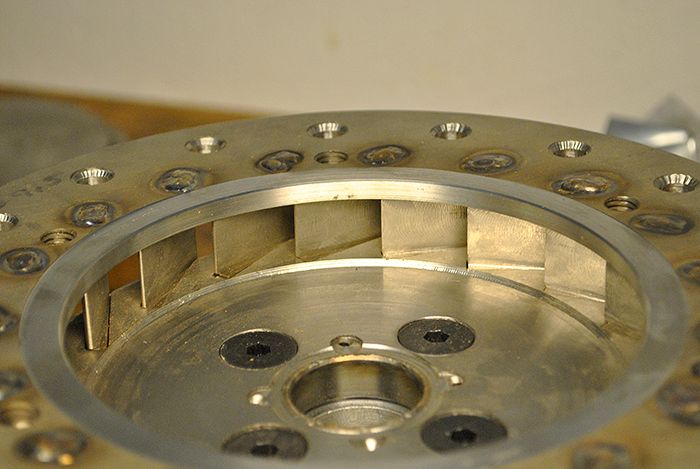 TV94 turbine wheel and some evaporator tubes in place for reference. 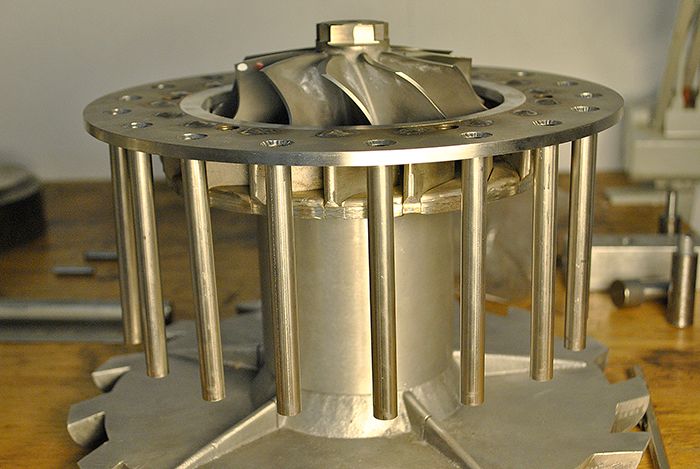 Next up will be to make the turbine cover from a chunk of mild steel that Olov had at home. 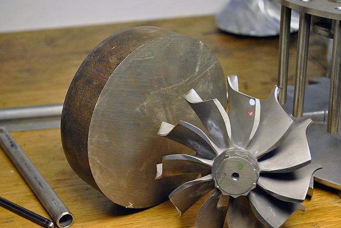 Cheers! /Anders |
|
|
|
Post by racket on May 5, 2016 17:11:25 GMT -5
Hi Anders
LOL..... You're making this look "easy" ;-)
Nicely finished off .
Cheers
John
|
|
|
|
Post by Johansson on May 6, 2016 1:17:12 GMT -5
Hi Anders LOL..... You're making this look "easy" ;-) Nicely finished off . Cheers John Thanks John, building the second engine is much easier since I know what needs to be done and in what order. The JU-01 was all uncharted waters for me so I had to think things through over and over again. Plus the CNC cut NGV and cast alloy diffusor has saved me countless tedious hours in front of the mill. :-) Cheers! :-) |
|
|
|
Post by jetjeff on May 6, 2016 3:19:05 GMT -5
Hi Anders,
Outstanding work! My hats off to folks tackling such a large project.
Jeff
|
|
|
|
Post by Johansson on May 7, 2016 0:17:53 GMT -5
Inspired by Patty´s journal bearing work I decided to fit mine as well. 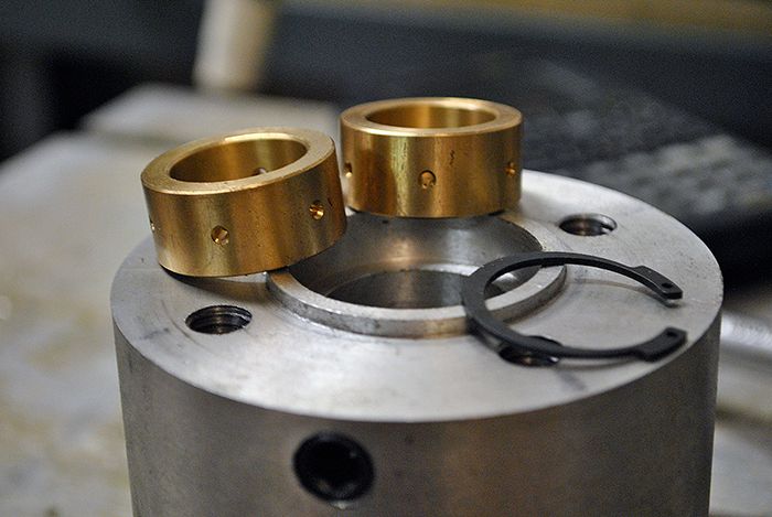 I had made a special tool for cutting the circlip grooves when I built JU-01, so it was just a matter blowing the dust from it and get busy. 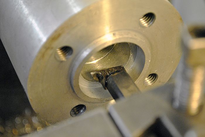 Here the rear bearings is in place, you can also see the oil drain from between the bearing and turbine shaft seal. 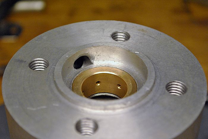 And here is the front bearing just behind the rear axial washer. An interesting detail about journal bearings (as you probably know) is that the bearing rotates inside the shaft tunnel with aprox. 50% of the rotor RPM, that is the reason I need to get the bearing tolerances just right. 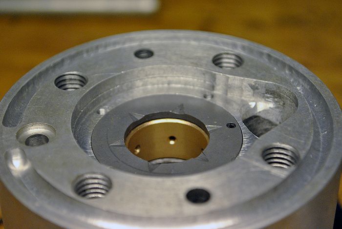 With the bearings in place I could measure where to drill the oil drain channel, since the g-forces will push the oil backwards I need to drain the oil as far towards the rear bearing as possible. 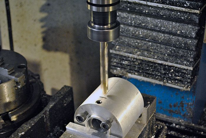 An o-ring seat was milled as well to make sure no oil will leak out. 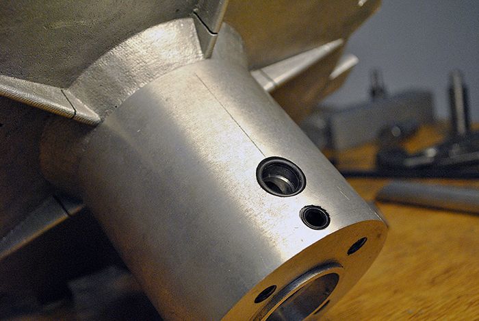 Since the combustor will be just outside the shaft tunnel I need to route the oil drain as close to the shaft tunnel as possible, else I would have used fancy couplings and a large radius on the drain line. 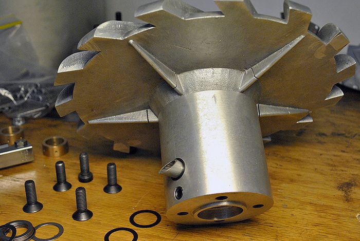 It will end up something like this, but I need to cast the compressor diffusor cover first before I can finish it. 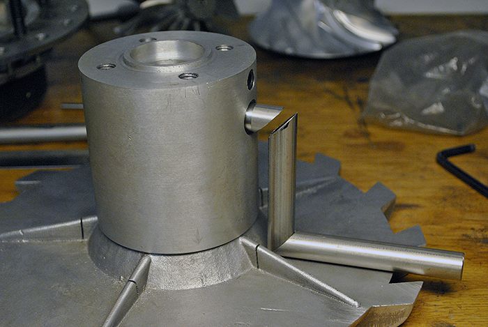 Cheers! /Anders |
|
|
|
Post by Johansson on May 11, 2016 13:47:51 GMT -5
To make the JU-02 much easier to field overhaul than JU-01 I will make the fuel supply external, on JU-01 there is an internal fuel plenum with silver soldered syringe injectors and to check the syringes for damage/blockage I need to remove the engine from the bike and take it apart completely. 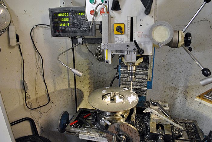 With an external fuel plenum I can easily remove one injector at a time with the engine fully assembled and still in the bike, a priceless improvement at race day when I don´t have time to tear the engine down between runs. 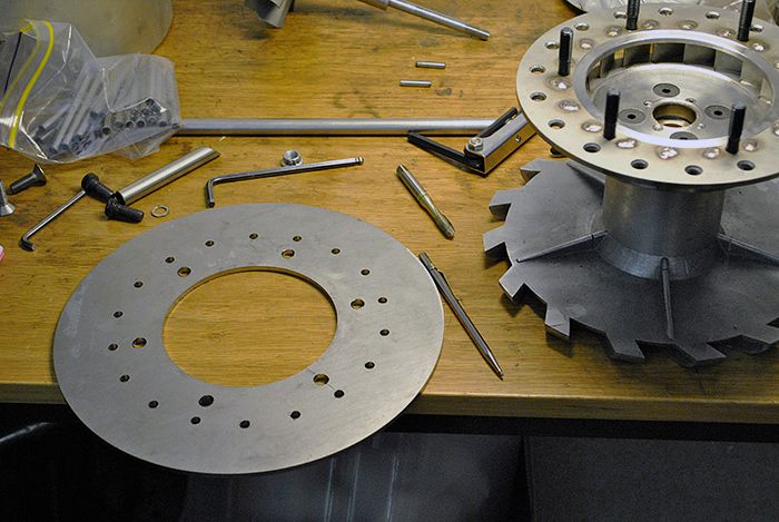 Here you can see the engine cover rear wall with six 10mm holes for the studs that bolts the engine cover to the NGV and 18 holes that will be threaded for the M8x1.0 banjo bolts that I will fit the syringe injectors to. 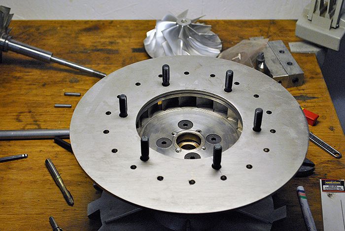 The turbine wheel cover will be sandwiched between the NGV and the engine cover rear wall to stay in place, I´ve just started to turn it from a solid chunk of mild steel that will be ceramic coated later. 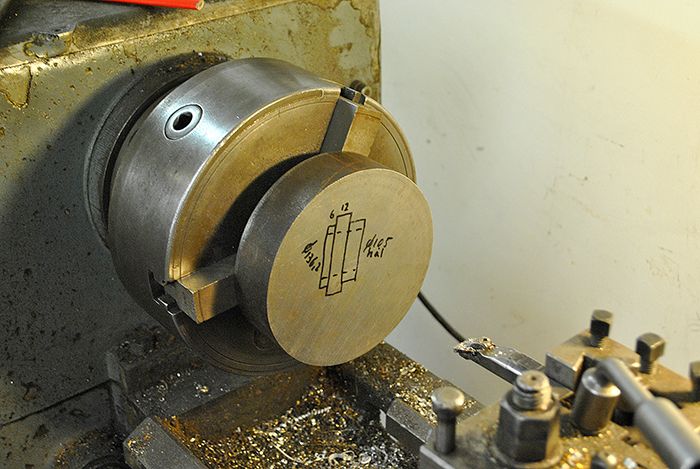 An hour into the job, there will be several more before the turbine cover is finished. 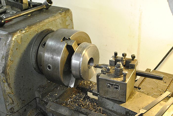 Cheers! /Anders |
|
|
|
Post by Johansson on May 14, 2016 17:53:16 GMT -5
To avoid the Eurovision Song Festival I escaped to the workshop to get some work done on the turbine cover. 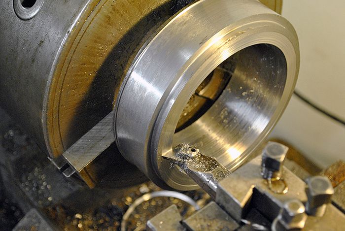 With the exducer diameter turned I put the turbine shaft in the small lathe and clocked the profile radius every 1mm with the indicator clock, here is the chart with the numbers. 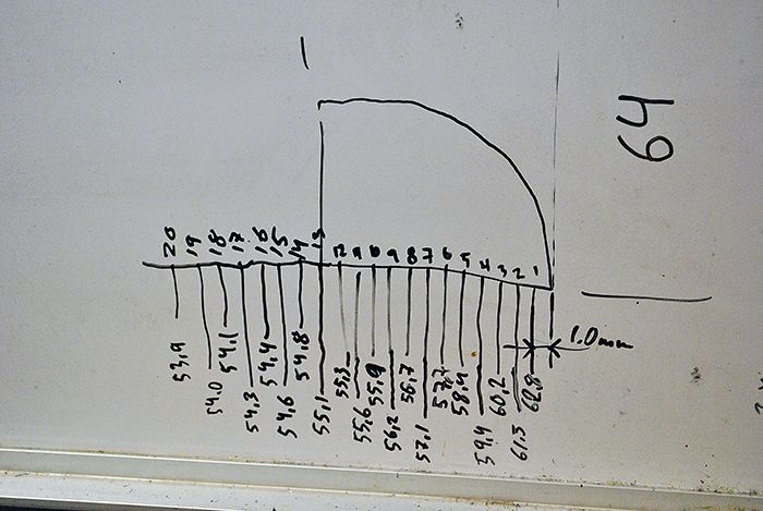 With that done it was a piece of cake to turn the turbine cover radius. 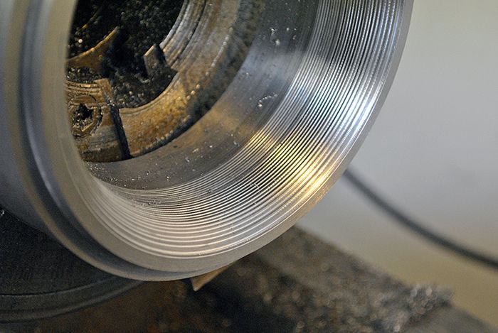 An hour or so was then spent on grinding the radius smooth. 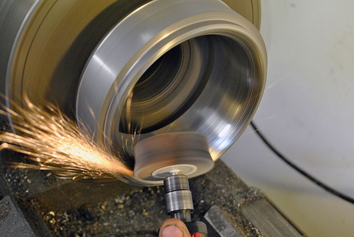 When the engine is completed I will put a layer of ceramic coating on the turbine cover, that has worked very well on JU-01. 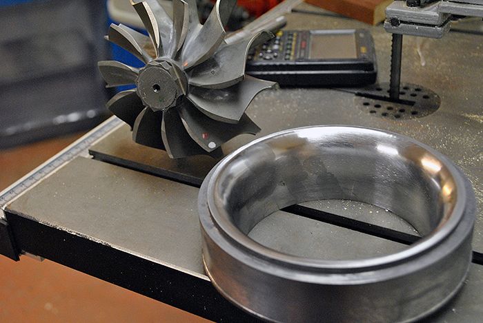 But will it fit? 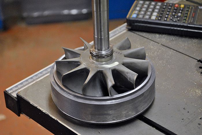 Yup, fits like a glove! 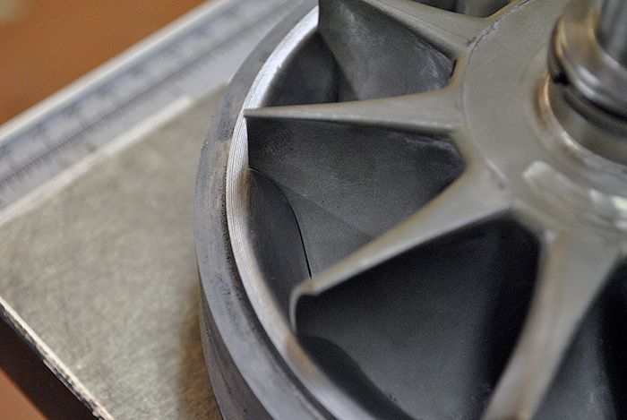 Here I am checking the axial clearance between turbine wheel and its cover. 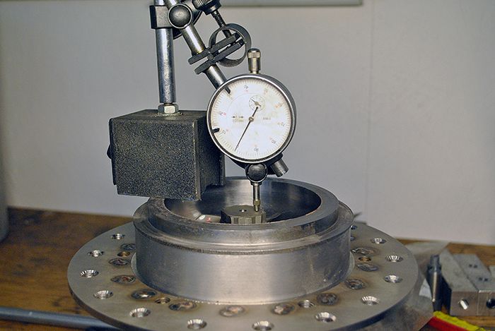 Time to turn the part around and make the seat for the casing rear wall and a groove for a v-band flange. 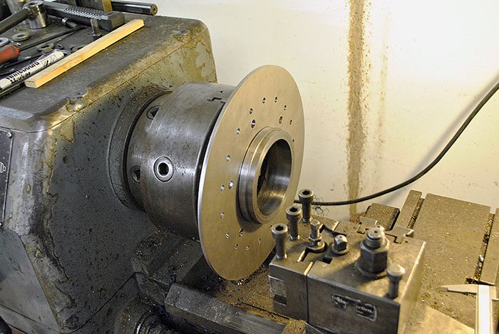 Here it is finished, I´ll make my own v-band clamp to get the exact diameter that I want. 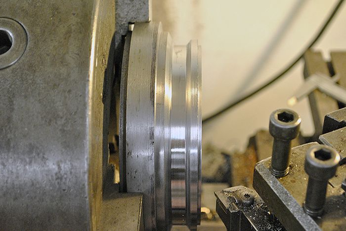 By now I could brush the grinding dust from my clothes and fit the parts together. 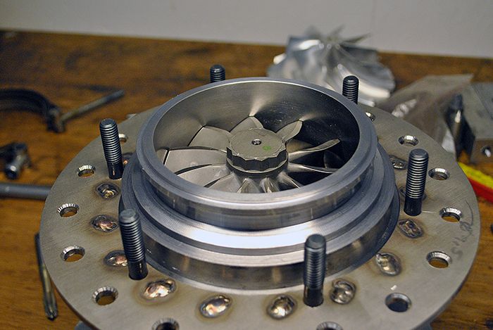 As you can see there is a 15mm shelf that the engine cover rear wall will rest upon, this shelf will act as a spacer so the air can get to the evaporator tubes. 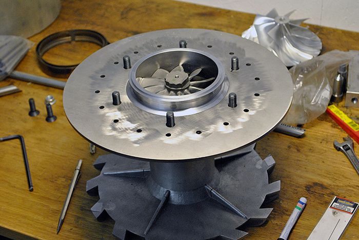 Here is a better view of the 15mm air space, I fitted an evaporator tube just so make it easier to see what is what. 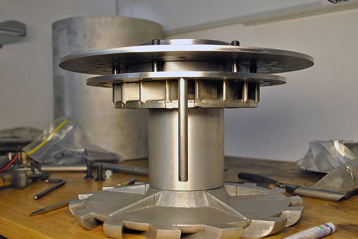 Cheers! /Anders |
|
dieselguy86
Veteran Member

Joined: September 2014
Posts: 186 
|
Post by dieselguy86 on May 14, 2016 19:45:49 GMT -5
Anders,
I dont know about everyone else, but to me you make it look easy making such a professional looking engine. Like your JU-01, im anxiously awaiting startup and running videos. -Joe
PS, how far are you from Sala?
|
|
|
|
Post by Johansson on May 15, 2016 0:28:51 GMT -5
Anders, I dont know about everyone else, but to me you make it look easy making such a professional looking engine. Like your JU-01, im anxiously awaiting startup and running videos. -Joe PS, how far are you from Sala? Thanks Joe, glad you like the build! It is always a compromise between keeping up the pace and being meticulous about every detail, I tend to cut corners where I can to actually get something done in an evening. Plus the lack of any drawings whatsoever makes construction much easier and a ton more fun. Sticking to drawings I made half a year ago is not my cup of tea, I like my projects interactive where I can decide the details as I go. I live 500km north of Sala in a village outside Östersund. |
|
gtbph
Veteran Member
Joined: August 2013
Posts: 101
|
Post by gtbph on May 16, 2016 4:39:16 GMT -5
Hi Anders,
I also think you're very productive, it's amazing how fast you make very nice looking parts! What counts is the result, and it does not look like cutting corners at all.
Cheers, Alain (who does not like the ESC either)
|
|
|
|
Post by Johansson on May 16, 2016 15:35:40 GMT -5
As I might have said before I will make an external fuel supply on JU-02 compared to the internal "standard" soldered syringe fuel ring I used on JU-01, it is easy to make but in order to check it for syringe blockage I have to tear down the entire engine which isn´t very practical at a race weekend. 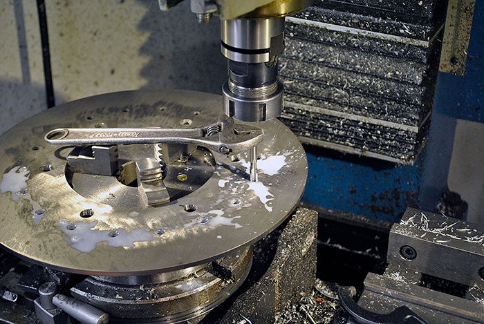 The solution is to complicate things a bit and make an external fuel supply, 18 separate syringe injectors will be fitted in banjo bolts and fitted through threaded holes in the engine cover rear wall pointing into the evaporator tubes. The banjo fittings will be shortened and silver soldered to a length of copper tube and then into a larger diameter circular plenum tube into which the fuel is fed from the pump. 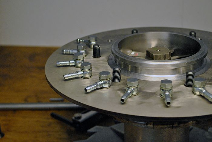 The injectors are made from turned down 3D printer nozzles threaded into the banjo bolt and drilled to accept a 0.7mm syringe needle that is silver soldered in place. This way I can take the injector apart for ultra sound cleaning during overhaul. 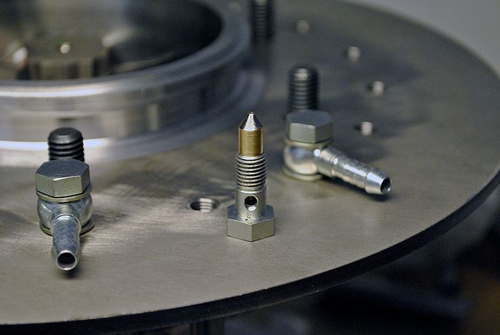 Here below is a picture of how the injectors will line up with the evaporators, the syringe needle will protrude into the bellmouthed entry of the evaporator and have a bend at the end so the kerosene hits the tube wall. 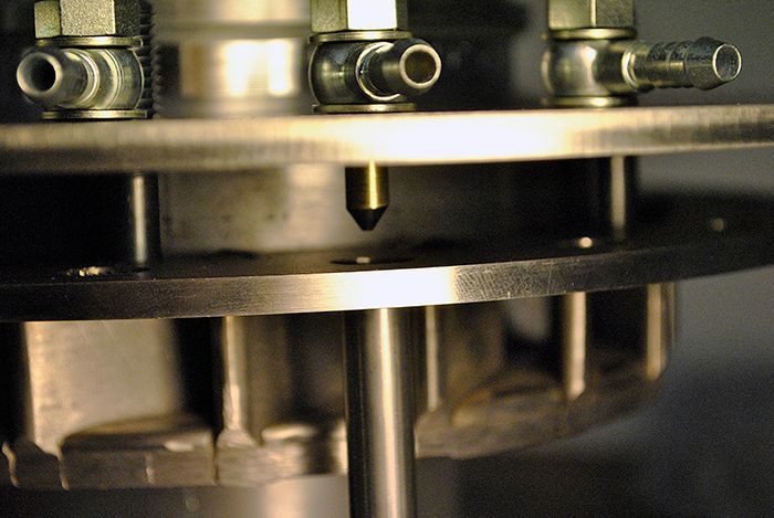 Cheers! /Anders |
|
|
|
Post by racket on May 16, 2016 15:57:08 GMT -5
Nice :-)
|
|