|
|
Post by smithy1 on May 16, 2016 17:10:10 GMT -5
Anders, excellent work mate and a brilliant idea, I would never have thought of doing that.
Not sure if you mentioned it previously, will you be "D-ing" the evap tubes??
Cheers,
Smithy.
|
|
|
|
Post by madpatty on May 16, 2016 21:48:16 GMT -5
Hi Anders,
Nice work there sir.
Can you tell me the approx ID of the syringe needles you will be using.
0.7mm is the OD i guess?
I have some 0.5mm ID and ~0.2mm ID nozzles at hand and i am confused which ones to use.
Thanks.
|
|
|
|
Post by Johansson on May 21, 2016 16:40:30 GMT -5
Making the fuel plenum is usually among the last things to do on a gas turbine build, but since I have been waiting for some spare parts for my 3D printer (they arrived today and it works again now!) so I can print the casting pattern for the compressor cover I had to find something to do. 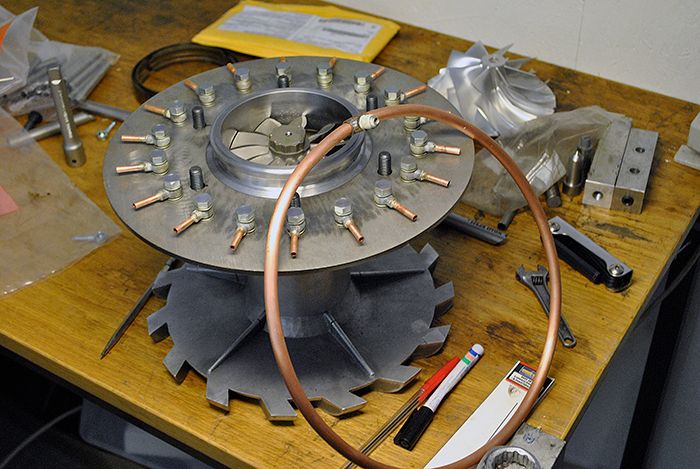 I cut the banjo fittings down and drilled them to accept a short length of copper brake line silver soldered to them, then I rolled a ring from a larger diameter copper tube as the fuel plenum and made an AN4 steel fitting that will be soldered in place where the copper tube ends meet. 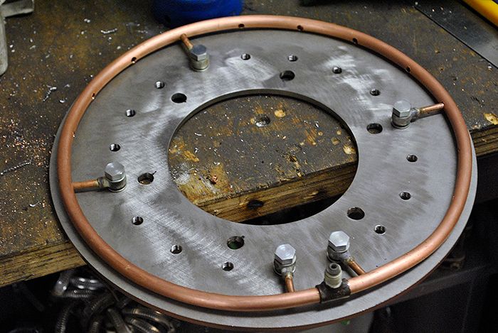 Unfortunately my hand held propane torch is too weak to heat up the copper tube ring enough so I have to borrow an oxygen/acetylen torch to solder it someday the upcoming week. 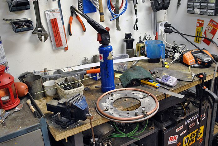 Time to get the casting pattern printed, I just need to fine tune the printer settings since I don´t want to screw up a 24 hour print.  Cheers! /Anders |
|
|
|
Post by Johansson on May 21, 2016 16:46:19 GMT -5
Anders, excellent work mate and a brilliant idea, I would never have thought of doing that. Not sure if you mentioned it previously, will you be "D-ing" the evap tubes?? Cheers, Smithy. Thanks, I just hope I won´t be cursed with never ending fuel leak issues from the banjo fittings... I´ll be D-ing the evaps in the same rig as the JU-01 evaps, since that combustor is performing very well I´ll try to copy it as much as possible for JU-02. Hi Anders, Nice work there sir. Can you tell me the approx ID of the syringe needles you will be using. 0.7mm is the OD i guess? I have some 0.5mm ID and ~0.2mm ID nozzles at hand and i am confused which ones to use. Thanks. Thanks Patty! Hmm, I honestly don´t know but I guess closer to 0.2mm than 0.5mm. I suggest you try the 0.2mm ID syringes first since the will produce a higher fuel line pressure which lowers the risk of uneven fuel distribution where the gravity feeds the lower syringes more fuel than the upper ones. Cheers! /Anders |
|
Chuks
Senior Member

Joined: August 2015
Posts: 498 
|
Post by Chuks on May 23, 2016 14:20:11 GMT -5
nice work you have done there JOHANNSON, you are making this look easy....
|
|
|
|
Post by Johansson on May 24, 2016 15:31:29 GMT -5
I have finally managed to repair my 3D printer, it was the flat cables to the print head that had become damaged from the constant flexing causing the heat control to stop working. I bought an upgrade kit with better cables so hopefully I won´t have this problem again. 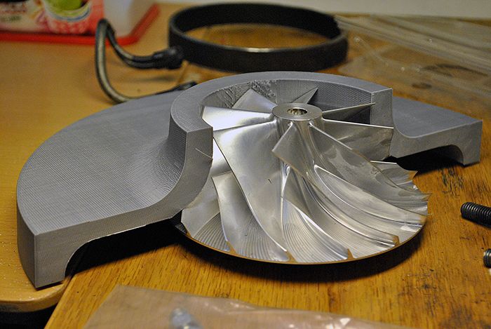 This morning I finished a 24 hour print of the first half of the compressor cover pattern, and the second is being printed as we speak. When they are both finished I will glue them together and coat the pattern until I get a smooth and finish with enough thickness to account for the casting shrinkage.  I also managed to borrow a propane torch to silver solder the fuel manifold. 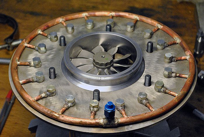 I think that the first job now is to get the compressor cover cast, then make the oil pipes that will enter and exit through the comp cover and after that make the combustor. No risk that I will find myself without anything to do this summer in other words.  Cheers! /Anders |
|
Deleted
Joined: January 1970
Posts: 0
|
Post by Deleted on May 24, 2016 16:25:52 GMT -5
Hi Anders
Looking good mate..... :-)
All Best
Andy
|
|
kevin
Junior Member
Joined: April 2016
Posts: 50
|
Post by kevin on May 25, 2016 1:10:33 GMT -5
Amazing build man... Your shop is drool- worthy!..
|
|
|
|
Post by livingweapon on May 27, 2016 12:04:54 GMT -5
Anders, amazing work as always - I just caught up with the 187 page bike thread. Congratulations on your successes to date, and nice to see the 3D printer being put to use supporting R&D. Also, great to see the accumulated wisdom coming together beautifully in JU-02. The integration of flanges, updated oiling, NGV 2.0, and fuel delivery enhancements are all brilliant. Please humor a n00b suggestion, especially if this was beat to death back in February, as I'm sure you have more on your mind besides the air box. Since the JU-01 diffuser cover slips into the air box, and has a small integrated bell mouth, it is closest to #5 in this post. It looks like you're already close to optimal. Your airbox floor looks low enough to avoid restriction below the bell (6 o'clock looking at the front of the bike), though there's room for curving the floor down between the lower frame rails if you have any doubt. Mainly, it looks like flush is the way to avoid a boundary choking the compressor. Last, a wider inlet neck on the JU-02 diffuser could act as a bigger transition radius, if there's room (front to back of the bike ...overall length of the JU-01 has things already looking cozy). Obviously you want to avoid stress from trying to clamp the compressor inlet neck to the tall air box, but close to flush as you can arrange seems to be the best bet.  Keep up the great work - can't wait to see what you get up to next! |
|
|
|
Post by Johansson on May 27, 2016 16:30:26 GMT -5
Anders, amazing work as always - I just caught up with the 187 page bike thread. Congratulations on your successes to date, and nice to see the 3D printer being put to use supporting R&D. Also, great to see the accumulated wisdom coming together beautifully in JU-02. The integration of flanges, updated oiling, NGV 2.0, and fuel delivery enhancements are all brilliant. Please humor a n00b suggestion, especially if this was beat to death back in February, as I'm sure you have more on your mind besides the air box. Since the JU-01 diffuser cover slips into the air box, and has a small integrated bell mouth, it is closest to #5 in this post. It looks like you're already close to optimal. Your airbox floor looks low enough to avoid restriction below the bell (6 o'clock looking at the front of the bike), though there's room for curving the floor down between the lower frame rails if you have any doubt. Mainly, it looks like flush is the way to avoid a boundary choking the compressor. Last, a wider inlet neck on the JU-02 diffuser could act as a bigger transition radius, if there's room (front to back of the bike ...overall length of the JU-01 has things already looking cozy). Obviously you want to avoid stress from trying to clamp the compressor inlet neck to the tall air box, but close to flush as you can arrange seems to be the best bet. Keep up the great work - can't wait to see what you get up to next! Hats off to you for reading through 187 pages of build thread! Thank you very much, the JU-02 design is, besides the obvious fact that it has a larger compressor stage, a result of the findings from the years of running and overhauling the JU-01. It will be much easier to work with and since most parts are either CNC cut or cast I can make a second engine with much less effort, the JU-01 was mostly hand carved chunks of alloy and mild steel so making another one would mean lots of tedious work. I mean, if the theoretical 270hp from JU-02 won´t be enough for the APS/Omega record then a pair of them in a larger bike chassis should do the trick... That flow chart was very interesting, I would have thought that number 3 would be the best flowing velocity stack. Pure luck for me then that I made the air box the way it is. JU-02 won´t have an air box at all, I´ll angle the engine slightly upwards to get it away from the rear wheel and to make room for a large intake screen. I´ve just finished epoxying the two 3D printed casting patterns together, this weekend I hope I can find some time to sand it down and get it ready for casting. Pics will come. Cheers! /Anders |
|
|
|
Post by racket on May 27, 2016 20:41:17 GMT -5
It'd be interesting to see a velocity readout when using a larger bellmouth of ~twice the throat diameter.
Good to know the airbox wall is providing reasonable flow conditions into your current bellmouth
|
|
|
|
Post by livingweapon on May 28, 2016 15:10:49 GMT -5
It'd be interesting to see a velocity readout when using a larger bellmouth of ~twice the throat diameter. Good to know the airbox wall is providing reasonable flow conditions into your current bellmouth John & Anders - I had also assumed #3 would be the winner, so it was a pleasant surprise when google turned up a credible side by side model. I suppose a bellmouth flush with a wall starts to look like an "infinite" bell width as wall radius increases, so long as front/sides of a box (screened cylinder?) are also at least that far away. Probably some multiple of inducer width or area gets +95% of the way to "infinite", and bigger than that is only interesting for stationary installations and yachts. Would be handy when mounting and screening JU-02 if it were as simple as "jet builder rule of thumb". However, the "looks good / also goes scary fast" model is kicking ar$e, so I'll sit back and continue to be impressed. Bryan |
|
|
|
Post by Johansson on May 28, 2016 15:25:24 GMT -5
Don´t hesitate to hollar in case you see something you have questions about, a good build thread isn´t only one way communication (even if a red thread is needed so the discussions don´t wander off too far...) I´ve printed the second half of the compressor cover pattern now, I was just about to print some lettering when the damn printer gave up on me again. It was the third time the micro SD card with the printer connection settings failed so I´ll have to wait for a new one to be shipped from the US...  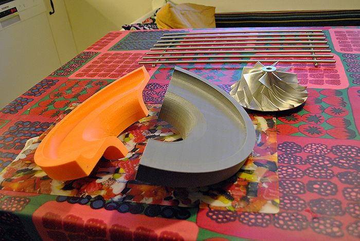 I glued the halves together with epoxy last night and it seems to fit quite well, I just need to add some filler around the inducer since the casting shrinkage would leave me with to large radial clearance otherwise. 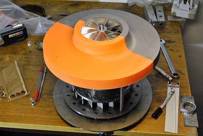 Cheers! /Anders |
|
|
|
Post by racket on May 28, 2016 18:08:00 GMT -5
Hi Anders
Love the pattern :-)
One thing I'm concerned about with the fuel manifold is the differential expansion between the fuel manifold and the injector mounting wall causing possible leaks , hopefully theres enough flex in the outer fuel ring to accommodate the variations.
Cheers
John
|
|
|
|
Post by Johansson on May 30, 2016 6:55:24 GMT -5
Hi John,
It turned out really well, it´ll be interesting to see how the casting ends up after the percentage of shrinkage and eventual warping.
The fuel manifold has some flex in it so hopefully it´ll be ok, if not I will find out in the test bench well before I fit the engine in the bike chassis. A leak at that location near the interstage duct during a >300km/h run might not have a good ending...
Cheers!
/Anders
|
|


