|
|
Post by Johansson on Mar 30, 2017 16:42:24 GMT -5
Hi Anders You guys are really getting into this build :-) Some serious speeds indeed with such a streamlined machine , those first jet fighter aircraft had <1,000 lbs of thrust . Nice solid shaft tunnel. Cheers John Hi John, We need to, Speed Weekend 2018 is fast approaching so no time for slacking around.  Our friends with the pulsejet sled has driven almost 250km/h sitting on top of the sled with 230kg of thrust, so I think that 300km/h is within reach if we get the engine running properly. Solid as a rock, it will be the anchoring point for the fan thrust so there is no reason to chase weight. By the way guys, Olov and I have finally started a Mobacken Racing facebook page, you can subscribe to it if you want at www.facebook.com/mobackenracing/Cheers! /Anders |
|
|
|
Post by Johansson on Mar 30, 2017 16:02:16 GMT -5
Thanks guys, this will be a fun build for sure! Plus it has the potential for some serious speeds. Here is the schematics for the engine, the two gas producers will feed into the C20 NGV and turn the power turbine which is fitted to the same drive shaft as the T700 fan. The rotational directions for the turbine and fan makes the arrangement look a bit weird with the gas producer exhaust pointing forward/upward but that we have to live with. 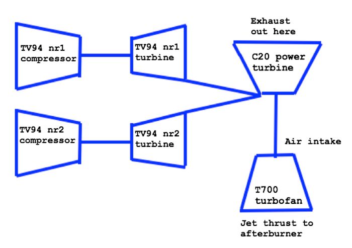 I started by machining away the welded in labyrint seal in the NGV to get a clean surface for mounting the NGV on the shaft tunnel. 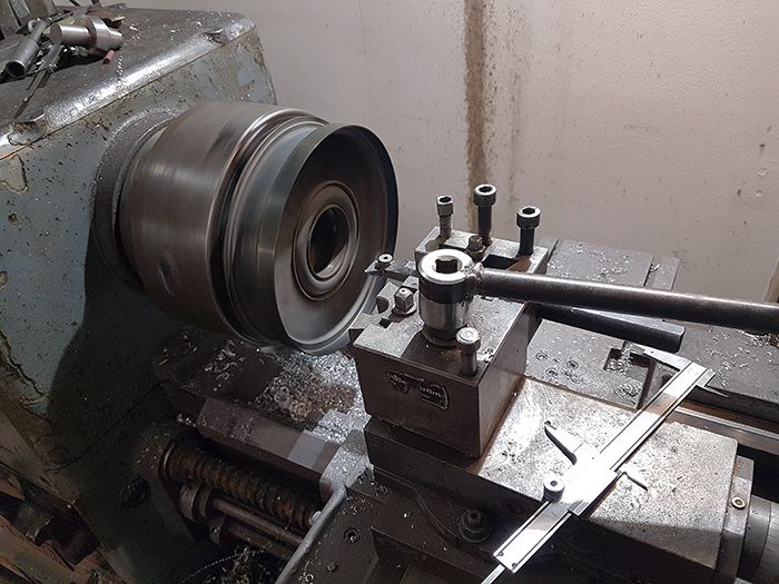 Then I bought a length of thick walled seamless 2142 steel pipe to make the shaft tunnel out of. 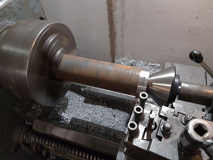 The NGV test fitted on the shaft tunnel. 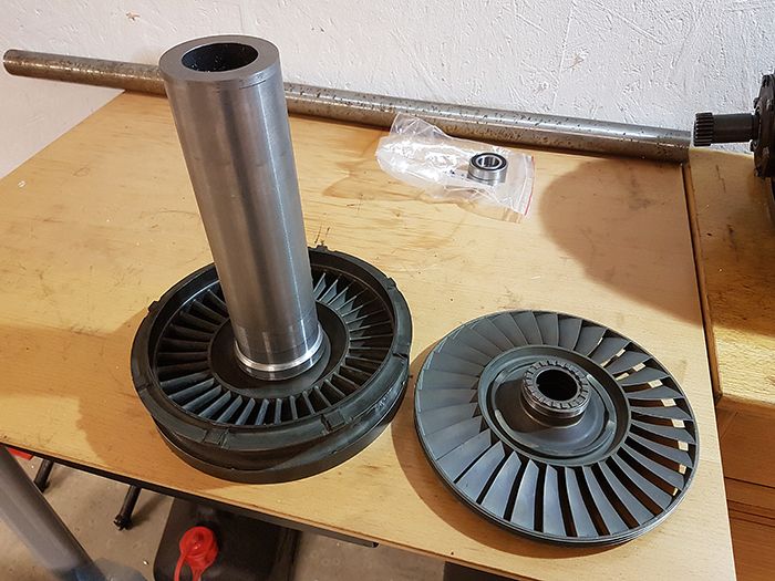 A pair of 3.5" v band clamps are ordered which will be the entry points for the sheet metal twin entry snail housing for the NGV, a pair of flexible exhaust ducts will later fit between the gas producers and the turbofan turbine to allow for some heat expansion. 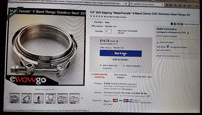 I will snatch a picture or two from Olovs progress on the chassis, or even better if he finds the time to post it here himself. I´ll ask him. Cheers! /Anders |
|
|
|
Post by Johansson on Mar 30, 2017 13:21:02 GMT -5
More assembly jobs done on JU-02. 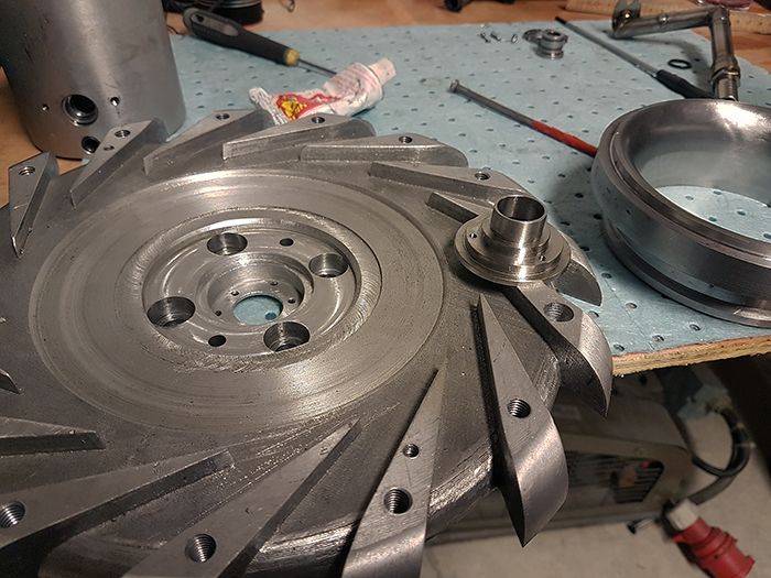 I´ve drilled all of the engine cover bolt heads for wire locking, managed to break all but one of my 1.5mm drills during the process... 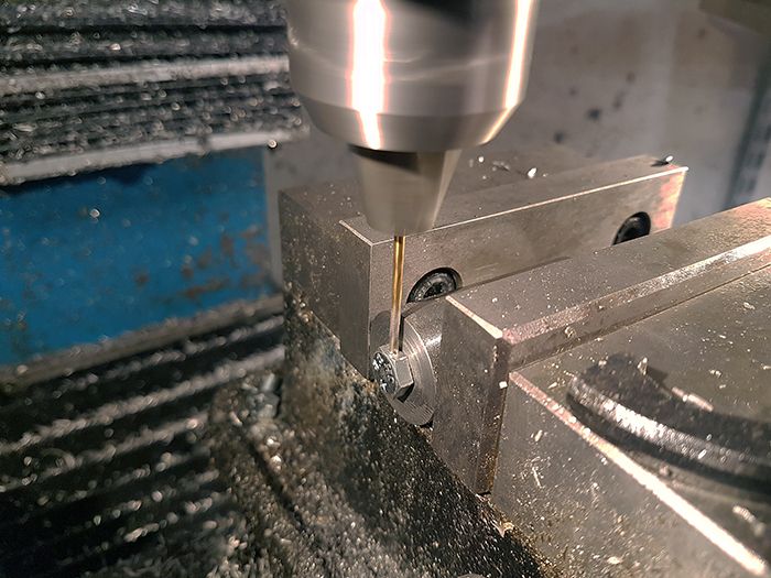 The scavenge line Loctited and wire locked. 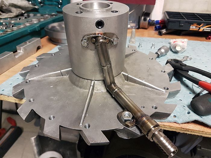 Torquing the NGV bolts to 70Nm with blue loctite. 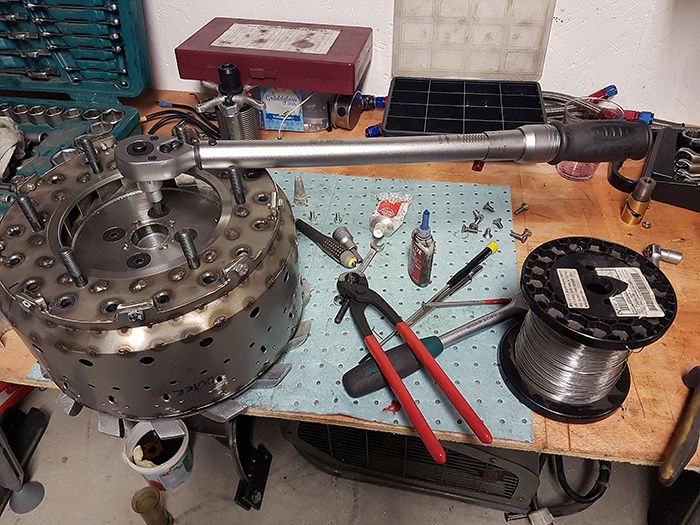 Here I am angle torquing the compressor nut, 130-145° is the recommended twist of the nut. 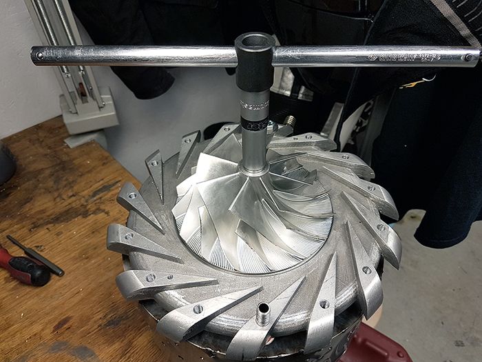 I am currently taking the last 0.1mm from the turbine housing to get the 0.6mm radial clearance John suggested. 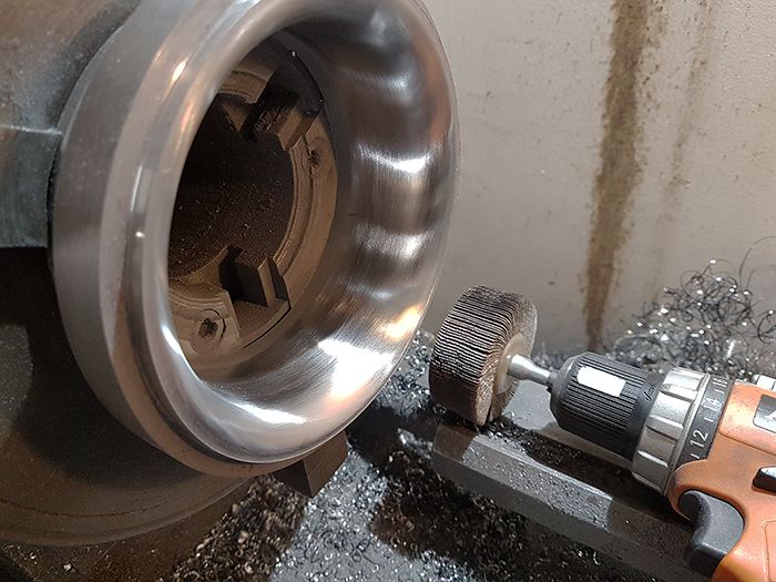 I have ordered a set of fancy stainless flanged hex socket screws for the compressor cover and engine casing, looks much better than the ordinary allen screws. 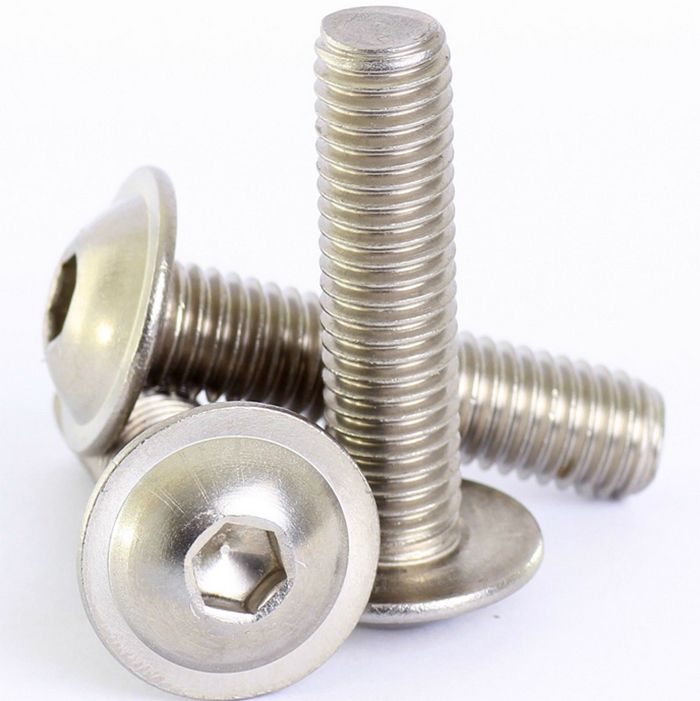 Cheers! /Anders |
|
|
|
Post by Johansson on Mar 30, 2017 11:54:27 GMT -5
As if we hadn´t enough to do already... 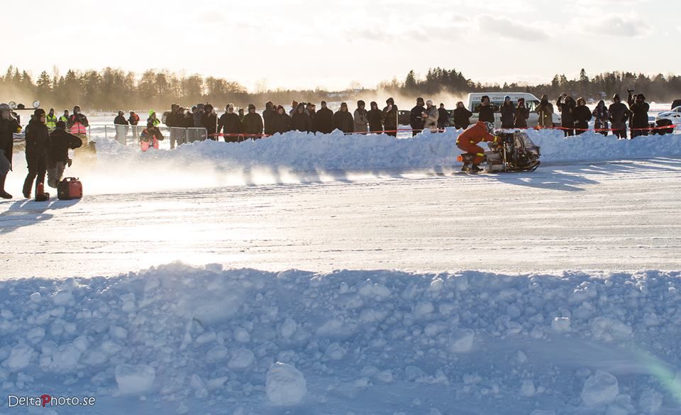 We ran the twinturbo jet kick sled this winter at Speed Weekend, finally the engines ran perfectly after a couple of years with oil pressure issues. Unfortunately the combination of hard ice, no brakes and unsharpened sled runners led to a crash when the kick sled steered hard left after engine shutdown no matter how Olov tried to keep it going straight.  According to the GPS log Olov hit the snow wall at 80km/h, he was very lucky not to get hurt. The kick sled was not so lucky, it tumbled a couple of times and was in a sorry state when he got back to the race pits... 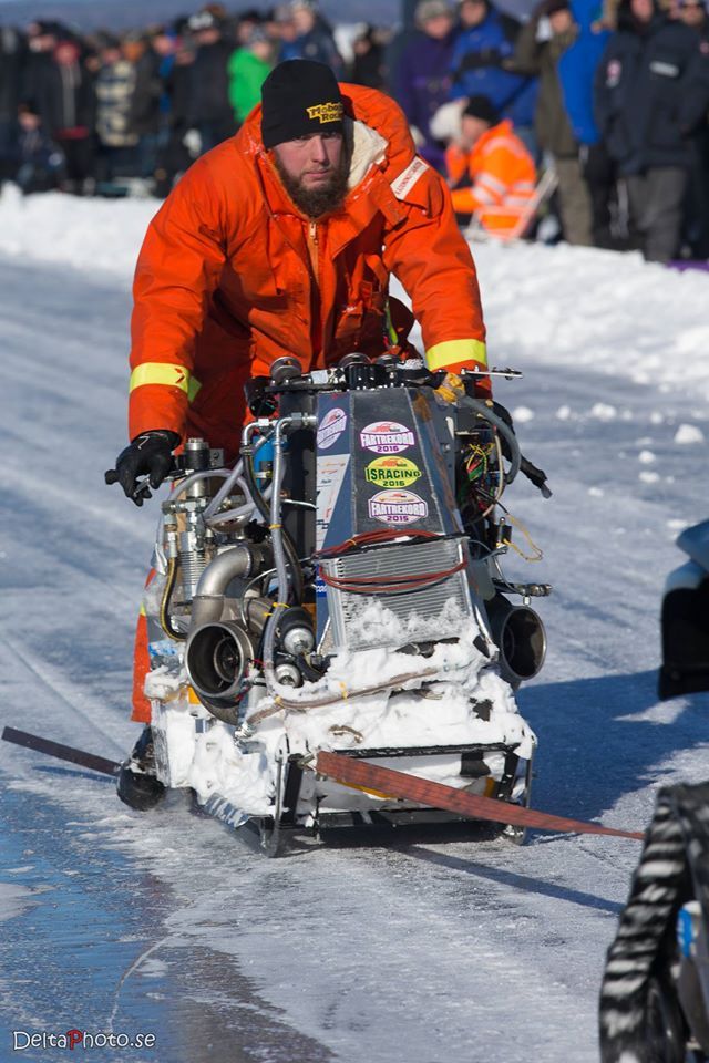 A week after the race we ran the engines without problems so they are ok. So, what would be do next? Despite a wide stance and a suspended engine cradle the kick chassis is simply too unstable at speed, so we need a change of plans! 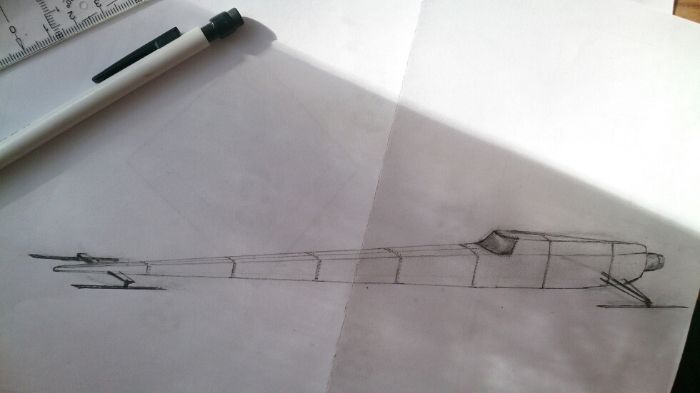 We have decided to build a top fuel style ice yacht powered by the kick sled gas producers coupled to a C20 4th stage turbine powered T700 1st stage axial compressor serving as a turbofan. Topped off with an afterburner of course, John has calculated the potential thrust with afterburner to over 500lbs! 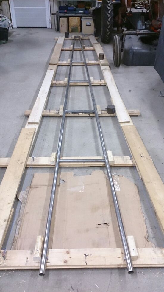 Since Olov and I are both family men there is little time for building anything together, so we have split the project so that Olov designs and builds the tubular chassis and I will build the turbofan module. John Wallis has kindly supported us with both a C20 4th stage NGV and the T700 fan, and we have figured out the main guidelines for the engine so the project is well on its way! 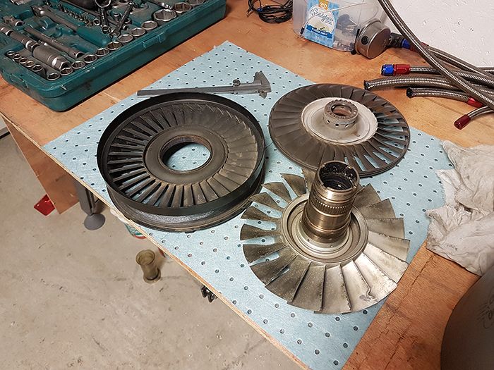 Cheers! /Anders |
|
|
|
Post by Johansson on Mar 29, 2017 16:53:27 GMT -5
Hi Anders, you mean something like that?  Cheers Ralph translate.google Hi Ralph, Exactly, a turbofan and power turbine combined in a single wheel. It would make a very compact and easy to construct thrust increaser, plus it would lower both noice and heat radiation from the engine which is a bit of a problem in a vehicle since things around an afterburner tends to melt... The best part about it in my mind is that it is something totally new, turbocharger based jet engines with afterburners have been around since Jesus wore diapers so it would be very fun to come up with a decently priced aft fan wheel for the community. With 100lbs of thrust from the gas producer and moderate ITT temps around 700°C, what kind of performance is reasonable to expect from such a fan properly designed? Cheers! /Anders |
|
|
|
Post by Johansson on Mar 29, 2017 6:48:31 GMT -5
Hi Alain,
No, I am building a more conventional turbofan at the moment. Build thread will come as soon as I have had time to sit down and write something up about it.
If I had the money to spare I would be very tempted to give it a try, but my workshop budget don´t allow any new projects at the moment.
It would still be very interesting to discuss this, perhaps a joined effort that one fine day would end up in a JATO aft-fan project? If we could decide on a gas producer size that is most common for us DIY:ers and bang our heads together we should be able to come up with a design for a fan, and with the number of members here it should be possible to raise funds for having a number of fans cast and tested by willing members.
The idea of a JATO community Aft-Fan project is really cool, we´d raise the bar for DIY jet engines quite a lot with the addition of a turbofan module instead of the old afterburner.
What do the moderators say? I am not at all skilled to do any designing but I am more than willing to use my JU-01 engine as a gas producer for testing the resulting fan with once it is retired from its service in the bike.
Cheers!
/Anders
|
|
|
|
Post by Johansson on Mar 27, 2017 1:12:26 GMT -5
Hi Anders Heh heh ..............18 months work is getting close to completion , all looking good :-) Cheers John Hi John, It sure is. I am most satisfied with the engine design regarding ease of disassembly/assembly, I have managed to simplify much of the JU-01 design so that there is a minimum of parts in JU-02. I can probably take the whole engine apart in five minutes without rushing it. Cheers! /Anders |
|
|
|
Post by Johansson on Mar 26, 2017 15:03:09 GMT -5
I finished the bellmouth add-on tonight, the compressor cover was put in the lathe and a groove for the v-band clamp was cut. I also cut an aligning edge so the bellmouth will center perfectly every time. 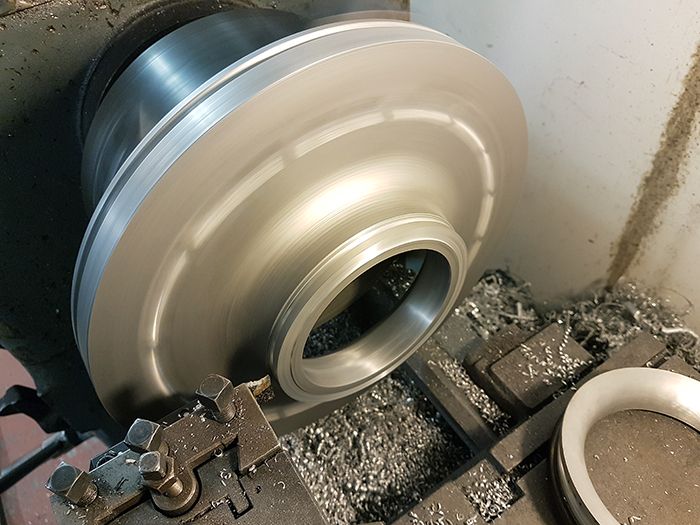 A matching edge was then cut in the bellouth piece. 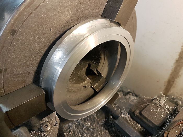 With that done I fit the two together and smoothed everything out with the shop air grinder and a soft sand paper disc until I couldn´t feel the edge any more. 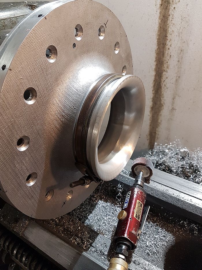 Like a glove! 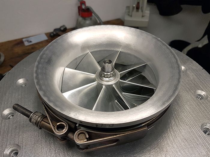 Next up is to take everything apart, clean it and drill all of the bolts and stuff for wire locking. 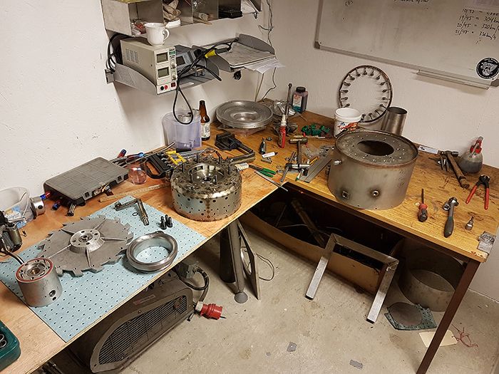 Cheers! /Anders |
|
|
|
Post by Johansson on Mar 23, 2017 16:46:19 GMT -5
Hi Anders Will it be possible to machine a shallow rebate into the comp cover snout with a matching one in the bellmouth so that there is positive concentricity between the two parts so that you don't need to fiddle with the V band during tightening to get things in alignment, very important not to have any sign of a step at the joint so close to the inducer . Jetpipe looking good :-) I'm getting excited , looking forward to seeing her assembled Cheers John Hi John, Actually I had planned to to that when I have the comp cover in the lathe for the v-band groove machining, I have made one that centers the jet nozzle flanges. V-band clamps are so very practical compared to the half dozen of small threaded holes and screws that was my first idea for bellmouth fastening, makes for very easy disassembly and no risk of dropping a small nut into the engine. I am too, the turbofan build will soon start to interfere with the JU-02 project but I hope to have the test stand ready before the summer so I can give her a spin when it is warm outside. Cheers! /Anders |
|
|
|
Post by Johansson on Mar 23, 2017 16:07:29 GMT -5
I found a little spare time to get some jobs done on the engine today. First off the jet nozzle was made, I turned a flange in the lathe and cut and rolled a jet nozzle in 1mm stainless. The angle of the picture fools the eye a bit, the nozzle looks straight but it is tapered. 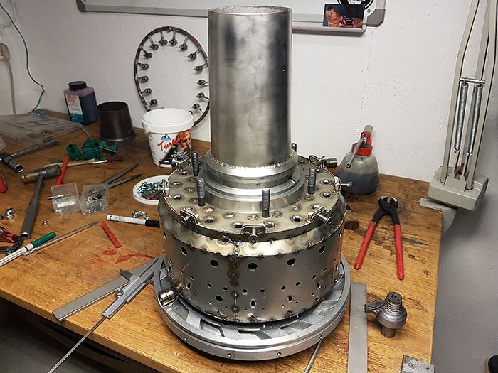 Here she is with her clothes on, the nozzle should get a much prettier color as soon as the engine is started. 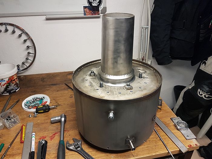 Then I managed to find a suitable chunk of aluminum so I scrapped my earlier idea with a 3D printed bellmouth and decided to make one out of alloy instead. 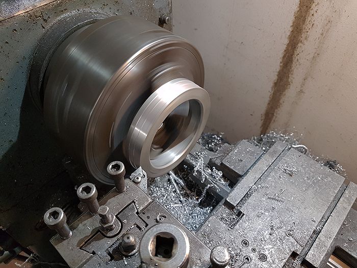 Here it has got its inlet radius and v-band flange groove. 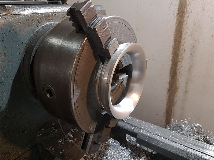 Milling the outside radius. 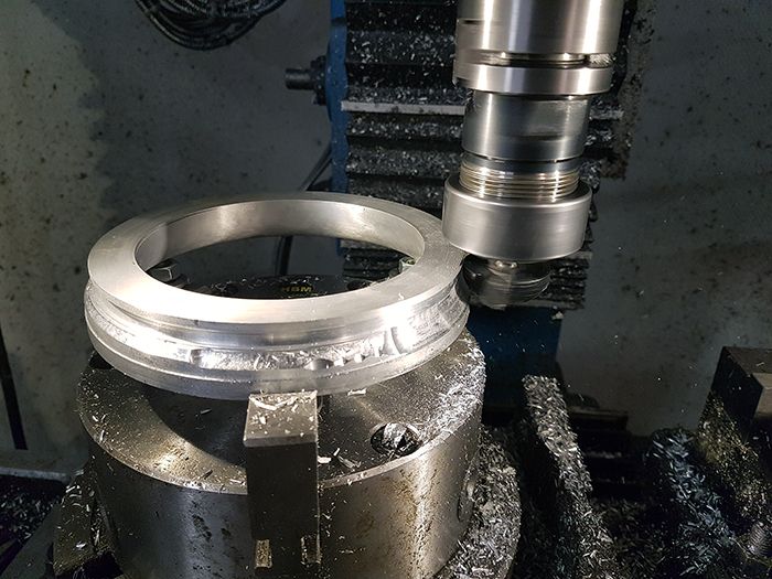 Olov lended me a v-band clamp so I had something so test fit it with, I haven´t cut the matching flange groove in the compressor cover yet so the bellmouth is just stacked on top of the cover in the picture. 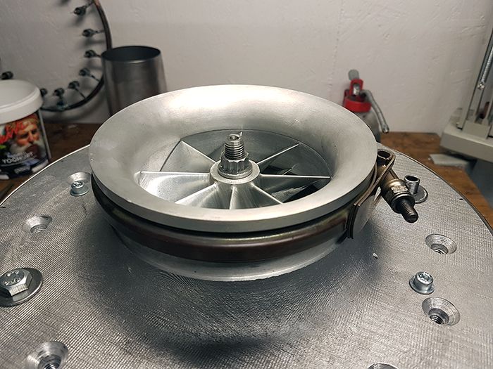 Cheers! /Anders |
|
|
|
Post by Johansson on Mar 21, 2017 16:53:25 GMT -5
Hi Anders That ain't going anywhere now. A bellmouth on the front, a jetnozzle on the rear and she'll be wanting to make some noise :-) Cheers John Hi John, Yup, a first start is getting pretty darn close. I asked Olov to pick up some material for the test rig for me since I cannot seem to fit 6 meter tubes in my Citroen C1... I´ll see if I can print out a nice bellmouth in PLA plastic for the compressor, later I will have to make an aluminum one with an integrated starter mount so there is no idea to overdo it just for a few leaftblower starts. Cheers! /Anders |
|
|
|
Post by Johansson on Mar 21, 2017 15:49:22 GMT -5
One of the few things left to do before the engine is ready to be mounted in a test stand was to secure the engine casing to the compressor cover, a job I had saved until last since it took a while to decide how to do it. 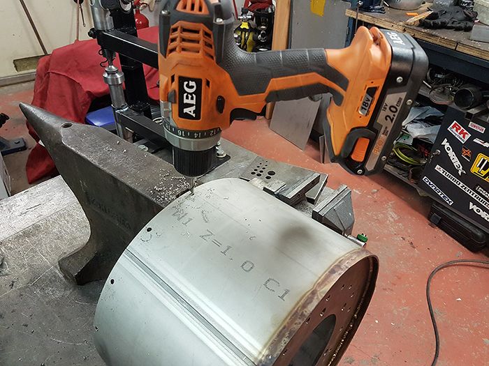 I drilled 18 5mm holes in the stainless casing, then I assembled the engine and continued drilling the holes into the cast compressor casing. I used a piece of tape on the drill to mark out the correct depth so I wouldn´t drill the holes through to the air passages. 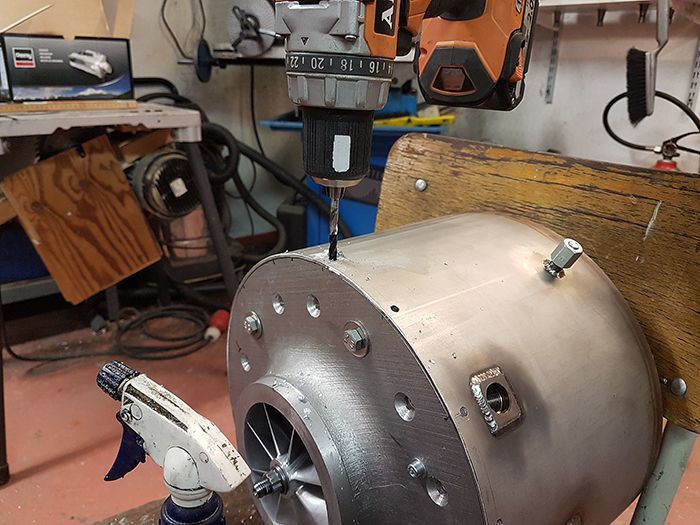 Threading the holes for M6 screws. 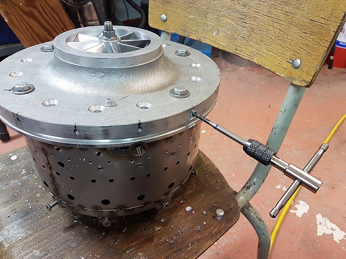 With the holes treaded I assembled the engine with the cover screws in place, this will certainly do! 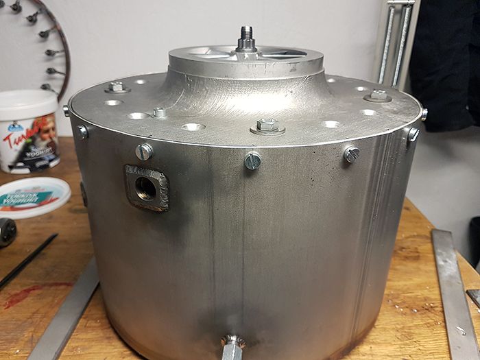 Cheers! /Anders |
|
|
|
Post by Johansson on Mar 19, 2017 14:58:02 GMT -5
As stated earlier I´ve been filtering the oil through an automotive filter for a while to get rid of any small foam particles that might be stuck in the tank. 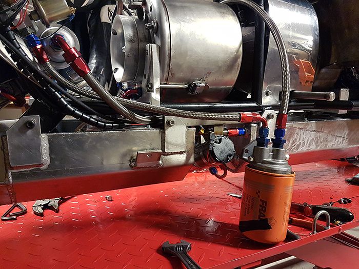 I have also been filtering the kerosene the same way, although the fuel pump has an intake screen that should take up most of any dirt in the system. After running the fuel pump at full speed for a couple of minutes I checked the pump screen and it was perfectly clean, so I think I am good to go. 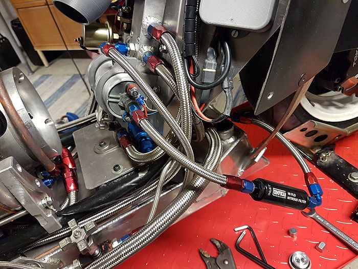 I will keep checking the inline filters after every run to see if there is anything in them, in case something blocks up the safety systems will shut the engine down before any damage can be done to it so I am not concerned at all. Cheers! /Anders |
|
|
|
Post by Johansson on Mar 18, 2017 16:46:22 GMT -5
Hi Anders, I think it might work in both fuel and oil tank as you've already proven it does even cope high temperatures. I don't know what's the specification of the foam you're using, but here's directly copied FAQ from JAZ fuel cell site: I have fitted the oil tank to the bike, filled it up and been circulating the oil back to the tank through an automotive oil filter to get all of the crap out of the tank before I run the oil into the engine. The pressure seems very stable despite that the flow must be much higher than during normal running since there is no restrictions in the oil line while pumping through the filter and back to the tank. So far so good, I´ll be filtering the oil a bit more later, I´ll keep it running while I work on other things in the workshop. I´ll do the same with the fuel tank later, I have a fine mesh steel filter (thanks Ernie for sending them in the goodiebag a couple of years ago!) that I will use for that. Easy to take apart and check for particles so I will keep filtering the kero until there is no more crap to be found. The real test is when I race the bike though, if I can brake hard without the engine shutting down I can consider the foam a smashing success. Cheers! /Anders |
|
|
|
Post by Johansson on Mar 17, 2017 14:54:34 GMT -5
Hey Anders, LOL! You're never too old to think about naked women, but at 55 you'll set your sights much lower. A full set of teeth would be nice, but not totally essential,,,lol. Jeff Ha ha! I find the expectations getting lower and lower for each passing year, still only at 35 but I miss the years when I could piss longer than I was tall... Hi Anders, Interesting idea to use foam instead of a more complicated baffle system to keep the oil where it should be, I've never heard of this before. I'd really like to know whether it works as good as it is supposed to work or not. That foam would safe me a lot work constructing a sufficient baffle system in my own oil tank. Laying awake and thinking tirelessly about some technical stuff is a bad habit of me as well...in fact that keeps me from getting enough sleep more often than my girlfriend does lol Cheers, Marvin Hi Marvin, I have gotten a handful of replies from fellow land racers about the foam, most tell me stories about blocked fuel filters and carbs from crap coming from the foam. Not exactly what I wanted to hear but very useful since I think I can sidestep this problem by filtering the oil/kero properly before letting it into the engine. Women keep you awake for half an hour, workshop problems keep you awake all night. Cheers! /Anders |
|


