miuge
Veteran Member

Joined: March 2014
Posts: 199 
|
Post by miuge on Jul 5, 2022 13:22:55 GMT -5
|
|
miuge
Veteran Member
Joined: March 2014
Posts: 199
|
Post by miuge on Jan 9, 2022 5:28:34 GMT -5
Hi,
Many Holset HX35, Schwitzer or BorgWarner S200 turbos come with approx. 50mm comp inducer and are matched with bigger turbine, also without internal WG, they are commonly available as used or cheap aftermarket units all over the world.
70mm freepower might not give any impressive performance figures without a gearbox and that's where things become complicated.
|
|
miuge
Veteran Member
Joined: March 2014
Posts: 199
|
Post by miuge on Dec 14, 2021 16:25:17 GMT -5
Hi John,
Have you checked injector flow pattern (fan, atomization) at higher fuel pressures? The fan looked pretty well atomized with that syringe test, but could that fan narrow down and pour fuel straight into the combustor at higher pressure levels? How high P2 pressures did Andy experiment with? Are the injectors identically shaped with Andy's engine?
Would be interesting to see what's happening inside the engine while running, would it be too much work to add a clear inspection window to see the front end of the combustor - what or when the carbon trails are caused and does it have something to do with the pulsation.
|
|
miuge
Veteran Member
Joined: March 2014
Posts: 199
|
Post by miuge on Nov 7, 2021 4:25:13 GMT -5
What sort of lathe? If its something like a small desktop lathe that might struggle, but even any half-decent manual lathe should be able to cut basically any tool steel (not hardened). Otherwise its because of wrong tools or user error.
|
|
miuge
Veteran Member
Joined: March 2014
Posts: 199
|
Post by miuge on Jul 29, 2021 15:39:41 GMT -5
The two aluminum and stainless won't weld together unless we're talking about some highly advanced laser welding or such, all you did was a mechanical bond. For your own safety, don't use that method for anything that should hold up pressure or flammable fluids.
|
|
miuge
Veteran Member
Joined: March 2014
Posts: 199
|
Post by miuge on Jan 14, 2021 17:25:01 GMT -5
Take a look at Subaru "Rocket anti-lag system" if not familiar:
|
|
miuge
Veteran Member
Joined: March 2014
Posts: 199
|
Post by miuge on Oct 8, 2020 12:33:10 GMT -5
Looks like we could make the diffuser as planned with the software we got. I'd like to run a scaled down test part on our machine first, then we could move on to real design process.
|
|
miuge
Veteran Member
Joined: March 2014
Posts: 199
|
Post by miuge on Sept 29, 2020 16:17:42 GMT -5
Thanks to Andy I was able to make the first rough sketch of the comp diffuser, same diameters/areas/angles were used. What I'm trying is to smooth out the passages slightly with gentle radiuses. Passage entries and leading edges obviously need more work in my design, hopefully after few long nights things will clear. I also need to check whether our CAM software can or cannot work around this kind of shapes. _diffuser_test_2(1).JPG?width=1920&height=1080&fit=bounds)
_diffuser_test_1.JPG?width=1920&height=1080&fit=bounds) |
|
miuge
Veteran Member
Joined: March 2014
Posts: 199
|
Post by miuge on Sept 23, 2020 14:28:04 GMT -5
Hi John,
Thanks for the tip, that's good to know. I've reached Andy and he is willing to share his information, am very thankful for that! Will be sharing our outcome as we proceed.
|
|
miuge
Veteran Member
Joined: March 2014
Posts: 199
|
Post by miuge on Sept 21, 2020 15:44:33 GMT -5
Hello people, It's been a few quiet months here meanwhile we have set up the new shop and learned a lot about CNC machining basics. Turning parts seem pretty straightforward with simple milling operations, this is what we've been doing last couple of months daily on repeat. Now I'd love to try some more complex milling operations and what I've been thinking as a good practise is a compressor diffuser, a nice symmetrical part within the capabilities of our CAM software. The question is, as our time is limited with the actual workpieces, could someone help with the math part of the project? We are not doing a commercial turbine, just a one-off hobby engine utilizing the machinery at the workplace. This could be another great showcase for what JATO forums is capable of  The parts I've already acquired are: -X856 comp wheel, 106*152*156*11.8mm
-HX82 turb wheel, 112*129*19mm
Eventually I'd like to run the engine in powerturbine configuration.  |
|
miuge
Veteran Member
Joined: March 2014
Posts: 199
|
Post by miuge on Apr 19, 2020 6:44:25 GMT -5
I guess many people are mislead by these YouTube videos of an axial DIY turbines. Some people consider it "working" if it spins by it's own power and well that's pretty much it. You can make a "turbine" like that bending some metal plates, stacking it up and put it in a can. YouTube will provide you all information to make such thing.
If you're about to build a real working turbine that would actually self sustain and produce thrust, take notes what John has pointed out, there's no easy way to do it.
|
|
miuge
Veteran Member
Joined: March 2014
Posts: 199
|
Post by miuge on Mar 29, 2020 5:34:05 GMT -5
Have been acquiring few of the most critical components for the build: -X856 comp wheel, 106*152*156*11.8mm -HX82 turb wheel, 112*129*19mm -HX82 rebuild kit -HGP-1A-F3 gear pump for oil system, 3cc/rpm -Digital tachometer 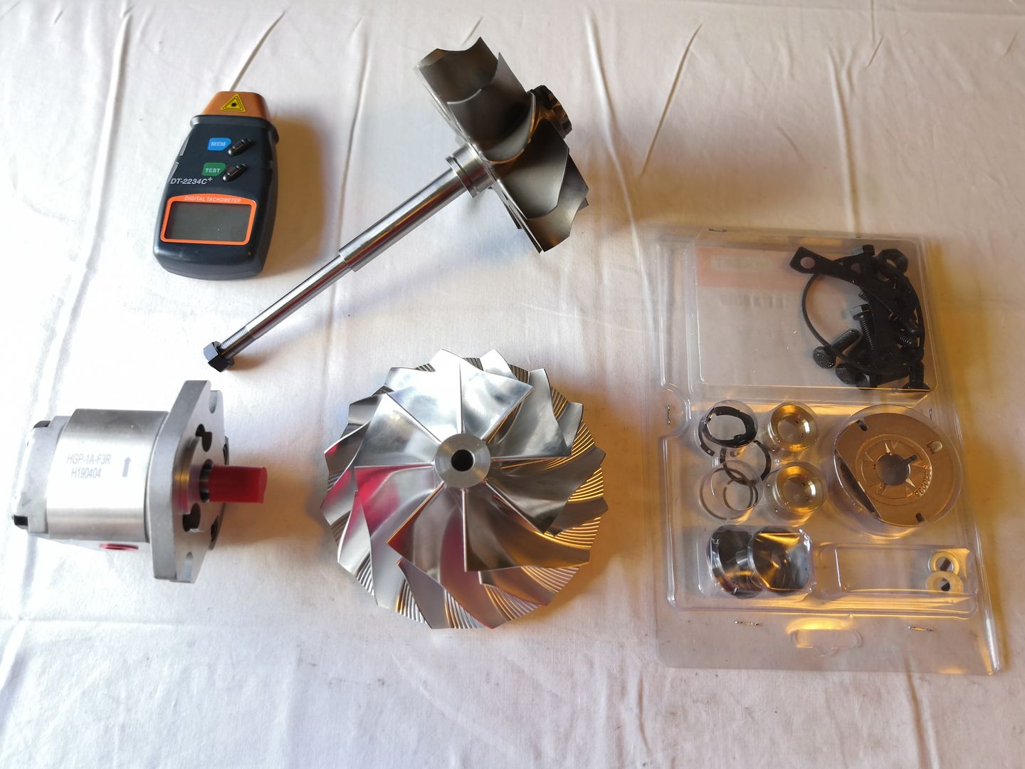 |
|
miuge
Veteran Member
Joined: March 2014
Posts: 199
|
Post by miuge on Jan 20, 2020 10:31:18 GMT -5
Consider making an air gap between the cap and the combustion chamber, so that the cap itself where you mount the fittings etc won't be glowing red hot. You'll also need the air gap if you're intended to add the swirler for the injector.
|
|
miuge
Veteran Member
Joined: March 2014
Posts: 199
|
Post by miuge on Jan 17, 2020 9:41:29 GMT -5
Hi John,
That's good news. Eventually the gas producer should be attached to a freepower unit and then a bike frame would be built around it.
I'm not sure if my notebooks are any better safe, been moving around and always cleaned up storages/archives that never seem so useful until you've got rid of them ...
|
|
miuge
Veteran Member
Joined: March 2014
Posts: 199
|
Post by miuge on Jan 16, 2020 18:39:51 GMT -5
I had various radial compressor documents and data collected, even some calculations made when I was last time delved into the topic, but now all that's missing, probably did too thorough cleanup for my computer... For some rational reason, I think, I ended up with the higher tip height and especially X856. On page 4 I found discussion where Chris (finiteparts) stated that higher tip height B would oppositely refer to a higher PR? John, are these pics any help determining the inducer tip angle? Got a reading 57-58deg from axial, equals 33-32deg? 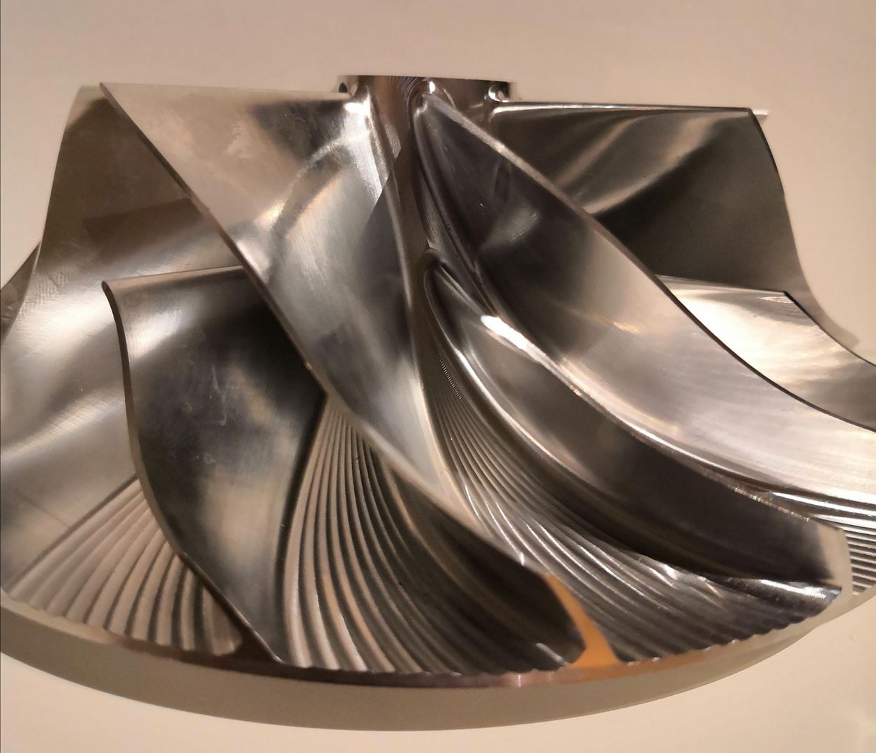 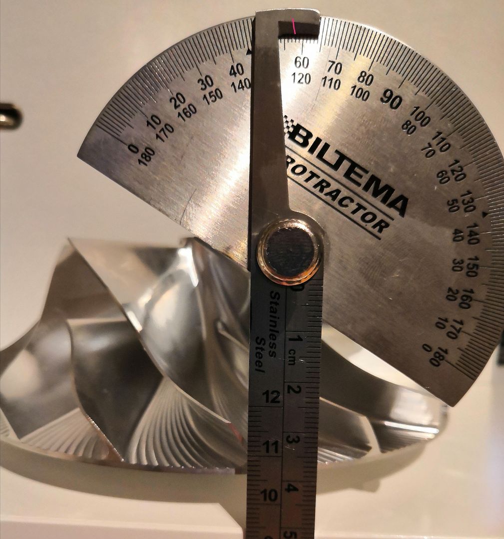 |
|


