300mm 75lb-thrust EDF: The Holy F&@kted Fan
Jan 19, 2018 13:40:08 GMT -5
Johansson, gtbph, and 7 more like this
Post by Feathers on Jan 19, 2018 13:40:08 GMT -5
Hey guys, I've got a new project in the human propulsion area:
Background: I'm an electrical engineer working at a Denver turbomachinery company. I'm used to designing >50kw high speed rotating machinery power systems. I've got a history in giant musical tesla coil design, as well as designing wearable tesla coils. I also lead a group at the University of Kansas in building a turboshaft-powered gokart from the ground up. Details at www.feathersengineering.com and on this jato thread.
A while back I remember seeing this video:
I was inspired, but disappointed to learn about the price and limited performance of the video's Schubeler EDF units for the purposes of human propulsion. Their systems are also $3k a piece. Following this, I ran a bit of a trade study of the most popular high performance EDFs to see what my ballpark design targets would be for a larger fan:
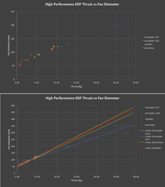
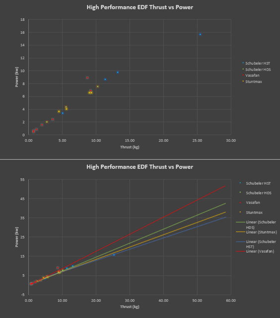
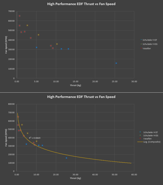
The primary limiting factor concerning fans approaching this size is clearly power system capacity. 300mm looks like a comfortable top-end for a project using existing power system components. Running ~10krpm, ~25kW peak power, and in the 35 kg-f thrust range. These numbers are probably a bit optimistic, considering I'll be scaling up a smaller design, but they should be ballpark.
TP Power Systems makes the 23kW-peak capable TP100 motor, I'll be specifying a 135kV wind and running 28s (smidge over 100V)
www.tppower.com/sort.asp?class_id=4&news=110
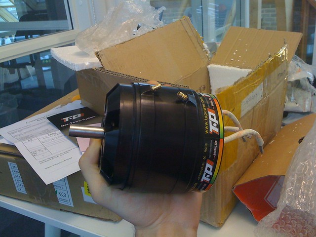
Alien Power Systems provides a 500A (overkill) 28s ESC:
alienpowersystem.com/shop/esc/alien-500a-28s-sport2-air-72-mosfet-esc-hv/
By now you can surely tell I'm more comfortable with high voltage systems. Less heat, less copper, less weight.
If you think 28s is a bad idea, our teslaguns (link in intro) run 16 turnigy nanotech 2200mAh 6s packs in series for the required ~400v bus.
And we strap them to our butt! (lower back)
They've been operating for years without issues.
Finally, all those kW will come courtesy of four 20 Ah Multistar 6s packs:
hobbyking.com/en_us/multistar-high-capacity-6s-20000mah-multi-rotor-lipo-pack.html?___store=en_us
Total power system cost is officially "up there" at around $1800 per fan, but I know what you guys spend on turbines, and this is Jetcat pro series territory.
---------Design Time----------
I'm not an aerospace engineer, and even my friends who are aerospace engineers researching fan design say that fan performance and design is pretty tricky. If they're struggling, I'd probably spend more time than it's worth trying to get it right.
Now you guys are familiar with forward velocity, efflux velocity, helix angle and AOA with respect to fans and props. My idea is as follows:
Most high performance fans I included in my trade study (above) run tip speeds of 300-400 mph. For a given forward velocity and efflux velocity target, that yields a certain helix angle and AOA.
Now if I simply scale one of these designs up from 120 to 300mm diameter, while maintaining similar tip speeds (reduce angular velocity), the helix angles, AOA, and blade profiles should still be very appropriate for the same target forward and efflux velocities.
With that in mind, I picked what appears to be a favorite, the Jetfan 120 pro, to scale off of. I like this fan in particular because it uses a thicker airfoil, which will be easier to fabricate via compression molded composite layup. More on that later.
So I got the rotating assembly in the mail:
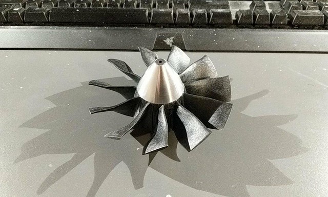
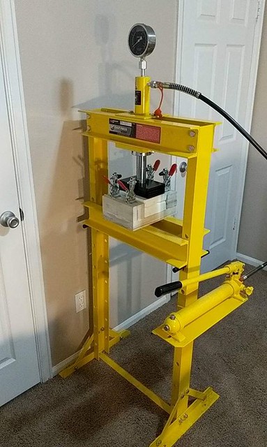
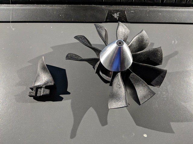
The hub is press-fit together, so I took it to an arbor press to release a blade or two, the reassembled to sit there and look pretty:
Now here's the tricky part. I need to digitize the blade profile, so I can reverse-engineer it and make it bigger. This means some sort of 3D scanning, which is generally expensive.
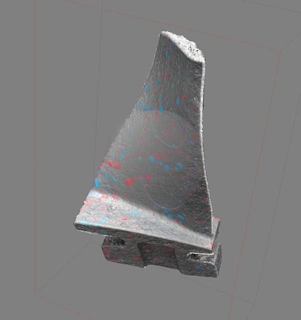
I chose a process called photogrammetry. Taking hundreds of photos of an object from different angles, then using software to correlate features and infer the object's shape. The glass-filled nylon blade has a fantastic (but featureless) surface finish, so I painted it matte gray, then gave it the "Jackson Pollock treatment". This will give the photogrammetry software (Agisoft Photoscan) some texture to chew on:
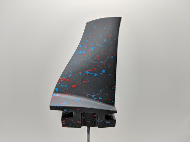
I set the blade up on some music wire, on a turntable inside a lightbox for even illumination. I took 117 photos while rotating the blade to catch all the important surface information:
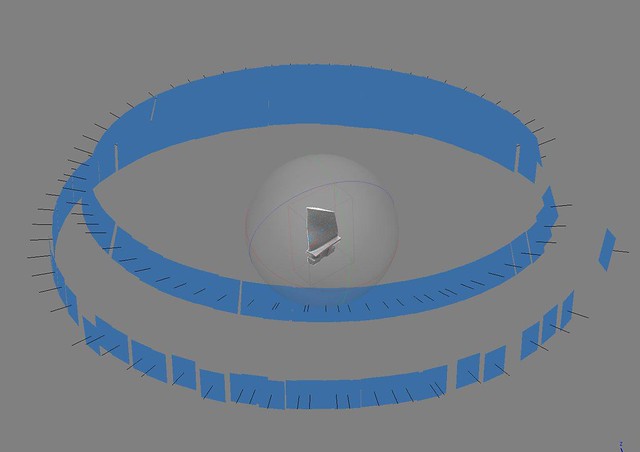
The results were pretty fantastic. Some root information was lost for lack of photos of that region, but I'm only after blade profile in this case:
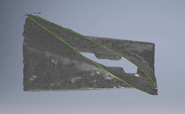
The next bit is a bit tedious. I imported the mesh into my cad suite (Autodesk Inventor) and used section views (20 of them) from root to tip to view the cross-section of the blade at that point. I then used sketch tools to produce a useful close approximation of the airfoil at these 20 points:
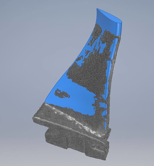
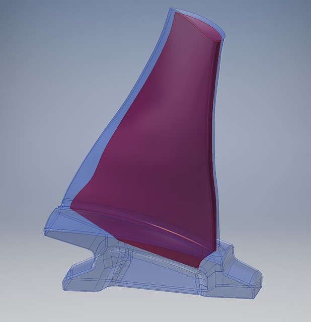
Lofting these sketches provides me with a full reverse-engineered blade profile to work from. Here it is, compared to the original mesh:
Next I need a root. Schubeler has plenty of experience with composite blades, and I figured they knew a thing or two about holding them in place.
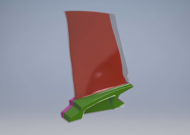
I produced a similar root geometry that allows me to clamp the blades in the same fashion as most other high performance EDF's:
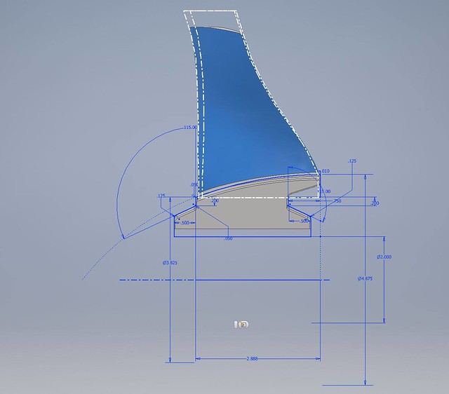
Some FEA at worst case conditions (full density, 30% fiberglass-filled nylon at 13krpm) yielded acceptable safety factors. The final blade will be a significantly lighter, significantly stronger carbon fiber sandwich composite, so I'm not concerned in the least about structural integrity:

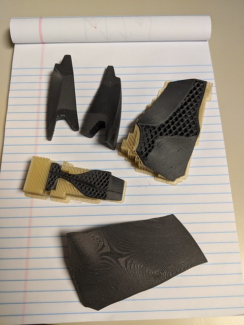
Now if a blade is to be a sandwich composite, it requires a core. The core doesn't need to be strong, it just needs to be very effective at conducting shear stress between composite skins on either side. I use a 3D printer extensively through all these designs, and they make carbon-fiber filled plastic filaments to print with. These filaments are not as strong as unfilled plastics (nozzle size prohibits fill fiber lengths sufficient to conduct significant stress), but they are incredibly stiff. Perfect use in a core:
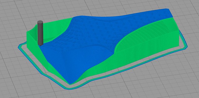
3D printing these complex geometries can be tricky. I'm using a water-soluble support material (PVA (glue stick stuff)) to hold up the build material (carbon-fiber filled PETG). The 20% honeycomb infill is a perfect internal structure for the blade core in this case:

Now I can sit here and CAD all day, but this is going to require some actual work.
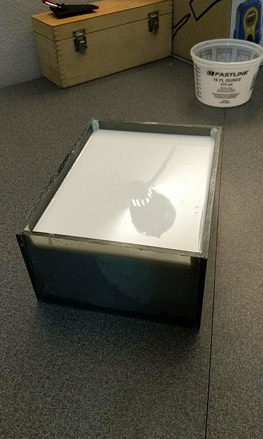
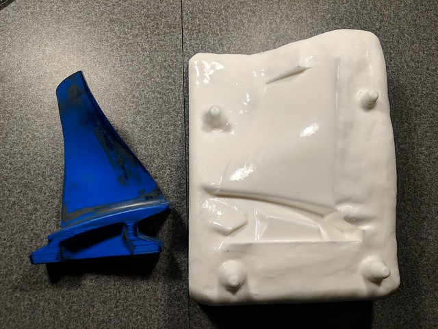
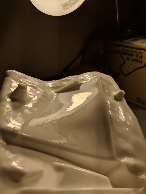
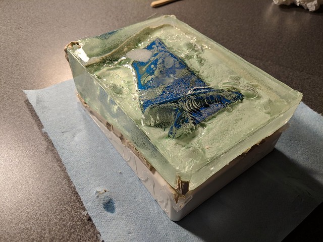
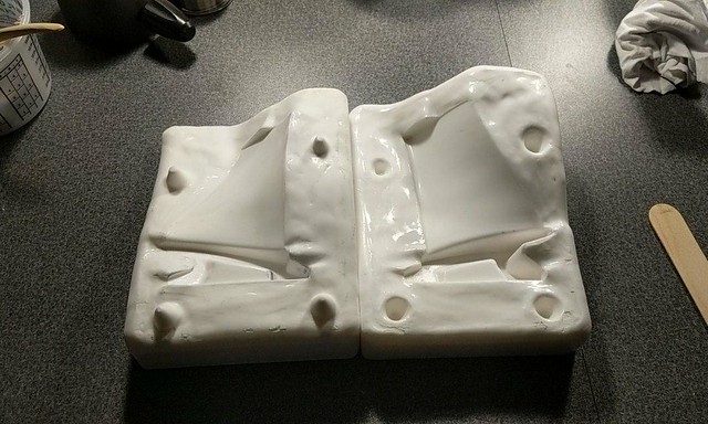
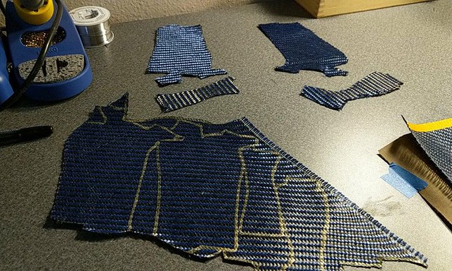
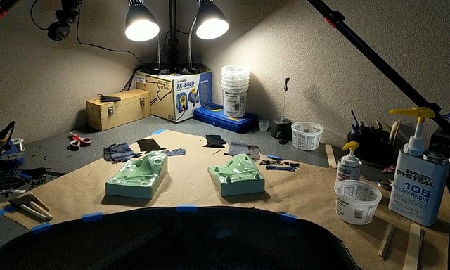
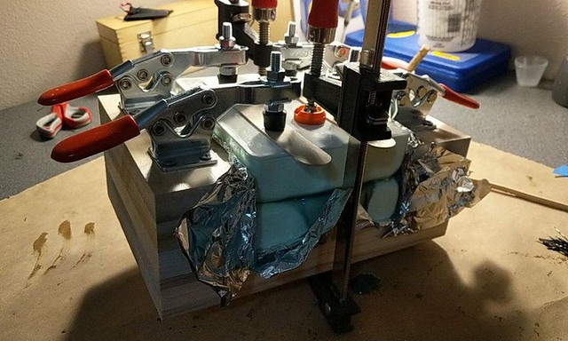
The blades will be manufactured using a hard urethane two-part mold. Resin, fabric, the core, and wet chopped fiber will be packed into either half as prescribed or necessary, and then the two halves will be closed. Closing should require a bit of force, and will squeeze much of the heavy resin out of the composite, helping keep weight consistent.
dag241 does an excelent job of explaining the process from mold production to composite part inspection and finishing. He doesn't use cores, bagging, or any method other than finger pressure during layup to remove resin from the fabric, so his blades are heavier than necessary, but this doesn't seem to impact their strength or performance to a significant degree:
Layup is going to be similar to hollow carbon fiber propeller blade manufacturing, except of course for the core in this case.
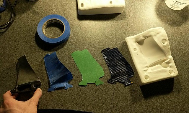
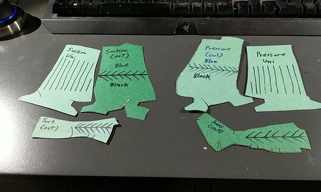
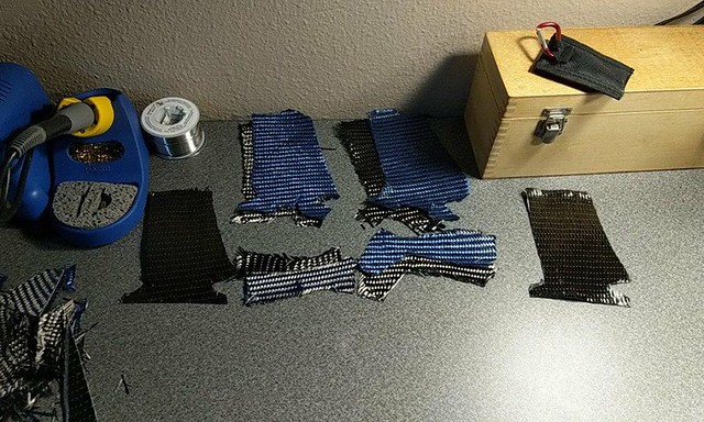
The root presents some very intricate and tricky geometry for a traditional layup. I intend to wrap at least one 3k biaxial layer over the root geometry in either mold half, then tightly pack the remaining space with an excess of resin-impregnated chopped fiber.
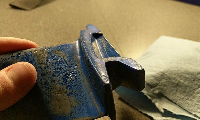
In order to produce the hard urethane negatives of the mold, I first need a butter-smooth blade positive. I 3D printed the blade geometry, then filled, sanded, repeated, until the finish looked acceptable:
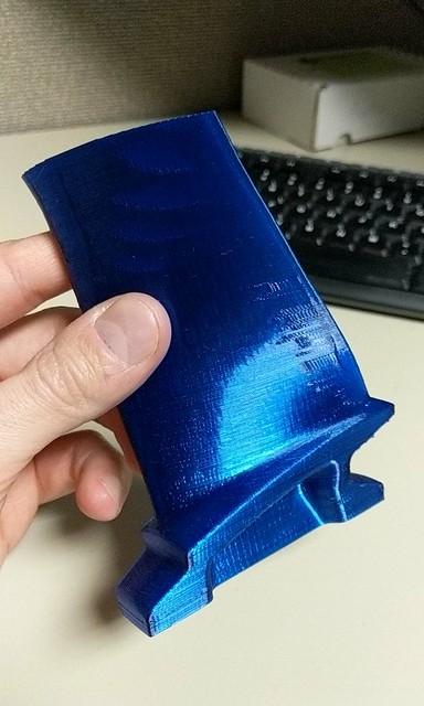
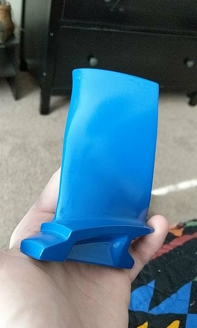
This is as far as I am right now. I've got my casting urethane, clay, release, and everything ready for the first pour. I have testing to do to make sure the urethane will let go of the positive I've been working so hard on.
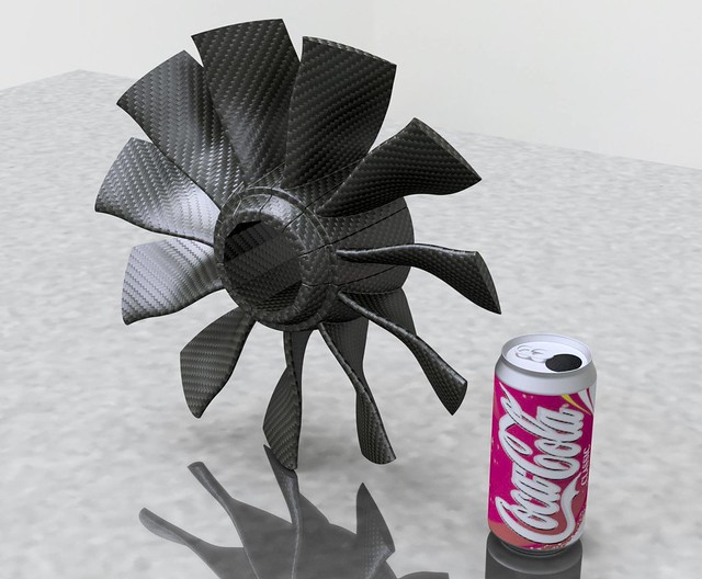
For now, here are some renderings of the rotating assembly as designed right now:
(coke can for scale)
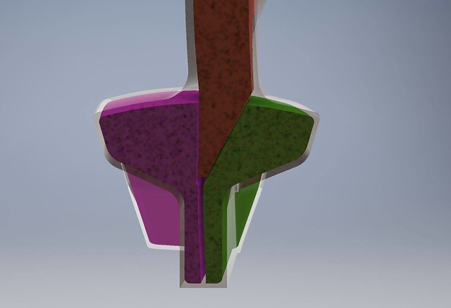
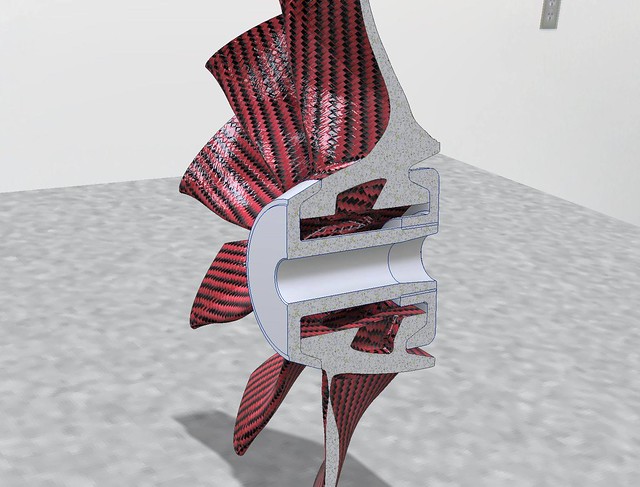
And a cross-section visualizing the forward and aft hub segments. These will threaded together with locking compound. The tapered bore accommodates the collet which will be used to mount the fan to the 12mm TP100 shaft.
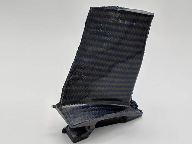
I should have some interesting first tries at compression molding a composite blade in the next week or so.
Cheers,
- Feathers
Background: I'm an electrical engineer working at a Denver turbomachinery company. I'm used to designing >50kw high speed rotating machinery power systems. I've got a history in giant musical tesla coil design, as well as designing wearable tesla coils. I also lead a group at the University of Kansas in building a turboshaft-powered gokart from the ground up. Details at www.feathersengineering.com and on this jato thread.
A while back I remember seeing this video:
I was inspired, but disappointed to learn about the price and limited performance of the video's Schubeler EDF units for the purposes of human propulsion. Their systems are also $3k a piece. Following this, I ran a bit of a trade study of the most popular high performance EDFs to see what my ballpark design targets would be for a larger fan:


The primary limiting factor concerning fans approaching this size is clearly power system capacity. 300mm looks like a comfortable top-end for a project using existing power system components. Running ~10krpm, ~25kW peak power, and in the 35 kg-f thrust range. These numbers are probably a bit optimistic, considering I'll be scaling up a smaller design, but they should be ballpark.
TP Power Systems makes the 23kW-peak capable TP100 motor, I'll be specifying a 135kV wind and running 28s (smidge over 100V)
www.tppower.com/sort.asp?class_id=4&news=110

Alien Power Systems provides a 500A (overkill) 28s ESC:
alienpowersystem.com/shop/esc/alien-500a-28s-sport2-air-72-mosfet-esc-hv/
By now you can surely tell I'm more comfortable with high voltage systems. Less heat, less copper, less weight.
If you think 28s is a bad idea, our teslaguns (link in intro) run 16 turnigy nanotech 2200mAh 6s packs in series for the required ~400v bus.
And we strap them to our butt! (lower back)

They've been operating for years without issues.
Finally, all those kW will come courtesy of four 20 Ah Multistar 6s packs:
hobbyking.com/en_us/multistar-high-capacity-6s-20000mah-multi-rotor-lipo-pack.html?___store=en_us
Total power system cost is officially "up there" at around $1800 per fan, but I know what you guys spend on turbines, and this is Jetcat pro series territory.

---------Design Time----------
I'm not an aerospace engineer, and even my friends who are aerospace engineers researching fan design say that fan performance and design is pretty tricky. If they're struggling, I'd probably spend more time than it's worth trying to get it right.
Now you guys are familiar with forward velocity, efflux velocity, helix angle and AOA with respect to fans and props. My idea is as follows:
Most high performance fans I included in my trade study (above) run tip speeds of 300-400 mph. For a given forward velocity and efflux velocity target, that yields a certain helix angle and AOA.
Now if I simply scale one of these designs up from 120 to 300mm diameter, while maintaining similar tip speeds (reduce angular velocity), the helix angles, AOA, and blade profiles should still be very appropriate for the same target forward and efflux velocities.
With that in mind, I picked what appears to be a favorite, the Jetfan 120 pro, to scale off of. I like this fan in particular because it uses a thicker airfoil, which will be easier to fabricate via compression molded composite layup. More on that later.
So I got the rotating assembly in the mail:

The hub is press-fit together, so I took it to an arbor press to release a blade or two, the reassembled to sit there and look pretty:

Now here's the tricky part. I need to digitize the blade profile, so I can reverse-engineer it and make it bigger. This means some sort of 3D scanning, which is generally expensive.
I chose a process called photogrammetry. Taking hundreds of photos of an object from different angles, then using software to correlate features and infer the object's shape. The glass-filled nylon blade has a fantastic (but featureless) surface finish, so I painted it matte gray, then gave it the "Jackson Pollock treatment". This will give the photogrammetry software (Agisoft Photoscan) some texture to chew on:

I set the blade up on some music wire, on a turntable inside a lightbox for even illumination. I took 117 photos while rotating the blade to catch all the important surface information:

The results were pretty fantastic. Some root information was lost for lack of photos of that region, but I'm only after blade profile in this case:

The next bit is a bit tedious. I imported the mesh into my cad suite (Autodesk Inventor) and used section views (20 of them) from root to tip to view the cross-section of the blade at that point. I then used sketch tools to produce a useful close approximation of the airfoil at these 20 points:

Lofting these sketches provides me with a full reverse-engineered blade profile to work from. Here it is, compared to the original mesh:

Next I need a root. Schubeler has plenty of experience with composite blades, and I figured they knew a thing or two about holding them in place.
I produced a similar root geometry that allows me to clamp the blades in the same fashion as most other high performance EDF's:

Some FEA at worst case conditions (full density, 30% fiberglass-filled nylon at 13krpm) yielded acceptable safety factors. The final blade will be a significantly lighter, significantly stronger carbon fiber sandwich composite, so I'm not concerned in the least about structural integrity:

Now if a blade is to be a sandwich composite, it requires a core. The core doesn't need to be strong, it just needs to be very effective at conducting shear stress between composite skins on either side. I use a 3D printer extensively through all these designs, and they make carbon-fiber filled plastic filaments to print with. These filaments are not as strong as unfilled plastics (nozzle size prohibits fill fiber lengths sufficient to conduct significant stress), but they are incredibly stiff. Perfect use in a core:

3D printing these complex geometries can be tricky. I'm using a water-soluble support material (PVA (glue stick stuff)) to hold up the build material (carbon-fiber filled PETG). The 20% honeycomb infill is a perfect internal structure for the blade core in this case:


Now I can sit here and CAD all day, but this is going to require some actual work.
The blades will be manufactured using a hard urethane two-part mold. Resin, fabric, the core, and wet chopped fiber will be packed into either half as prescribed or necessary, and then the two halves will be closed. Closing should require a bit of force, and will squeeze much of the heavy resin out of the composite, helping keep weight consistent.
dag241 does an excelent job of explaining the process from mold production to composite part inspection and finishing. He doesn't use cores, bagging, or any method other than finger pressure during layup to remove resin from the fabric, so his blades are heavier than necessary, but this doesn't seem to impact their strength or performance to a significant degree:
Layup is going to be similar to hollow carbon fiber propeller blade manufacturing, except of course for the core in this case.
The root presents some very intricate and tricky geometry for a traditional layup. I intend to wrap at least one 3k biaxial layer over the root geometry in either mold half, then tightly pack the remaining space with an excess of resin-impregnated chopped fiber.
In order to produce the hard urethane negatives of the mold, I first need a butter-smooth blade positive. I 3D printed the blade geometry, then filled, sanded, repeated, until the finish looked acceptable:


This is as far as I am right now. I've got my casting urethane, clay, release, and everything ready for the first pour. I have testing to do to make sure the urethane will let go of the positive I've been working so hard on.

For now, here are some renderings of the rotating assembly as designed right now:
(coke can for scale)

And a cross-section visualizing the forward and aft hub segments. These will threaded together with locking compound. The tapered bore accommodates the collet which will be used to mount the fan to the 12mm TP100 shaft.

I should have some interesting first tries at compression molding a composite blade in the next week or so.
Cheers,
- Feathers


