|
|
Post by cchange4us on Jan 20, 2020 7:46:47 GMT -5
Hi John Good old Bunvegas... I do love the place. I just read through your build thread then, the power turbine scroll really must have been a pain! Sheet metal has a mind of its own when it goes through thermal cycles. I remember a few years ago i was welding a rocker panel to an old Volkswagen. Everything was tickety-boo until i melted together the last 100mm of thin butt weld... bam, just like that i had 1mm of door gap near the latch. Still a bit of a sore point for me to this day lol. I need everyones advice as to the size and placement of the Primaries, secondaries and.... third-lees. The combustion chamber will no doubtedly go through changes once i update it to reflect the real world tube/sheet metal sizes (ie, once i get my hands on a empty fire extinguisher. With that said though, i still believe it is a good idea to consult the council of red hot whirly durly's and get an inital opinion - am i going in the right direction with this? 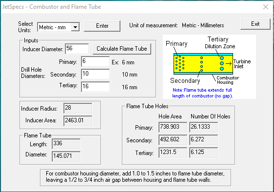
 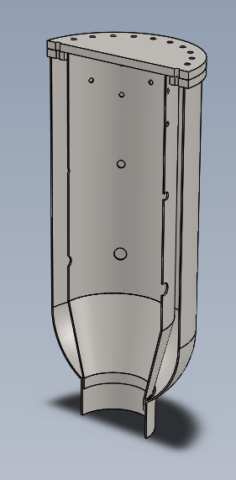 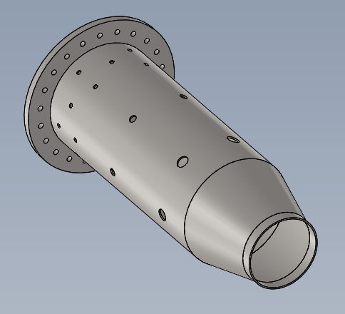 Smaller details such as the bolted flange at the top of the CC will be sorted out later. I'm thinking that the configuration that i modelled will surfice. If neccessary i could find some super-high temperature sealent to use or possibly cut a high temperature gasket for the job. |
|
miuge
Veteran Member
  
Joined: March 2014
Posts: 200 
|
Post by miuge on Jan 20, 2020 10:31:18 GMT -5
Consider making an air gap between the cap and the combustion chamber, so that the cap itself where you mount the fittings etc won't be glowing red hot. You'll also need the air gap if you're intended to add the swirler for the injector.
|
|
|
|
Post by racket on Jan 20, 2020 18:50:25 GMT -5
If you intend to eventually use liquid fuel its probably better to take the time to build for that , LPG will burn in "anything" so no problems getting the kero combustor to fire up on LPG , it'll only require some minor injector mods
|
|
|
|
Post by cchange4us on Feb 1, 2020 2:42:43 GMT -5
If you intend to eventually use liquid fuel its probably better to take the time to build for that , LPG will burn in "anything" so no problems getting the kero combustor to fire up on LPG , it'll only require some minor injector mods So i went away and did a bit more research on what is needed for my project. I had some old fire extinguishers laying around and i will be using them to make the combustion chamber and flame tube. The flame tube is 144mm in diameter and the combustion chamber housing is 179mm respectively, leave approximately 16mm gap when accounting for sheet thickness. With a 54mm diameter compressor inducer i will be requiring 2290mm^2 worth of flame tube hole area. I got giddy and cut some "swirlers" into the top of the flame tube, all up i estimate that there is 100mm^2 there. In all honestly im not sure how much "swirl" they will add to the combustion however i though it was worth adding in. Here is my plan so far: 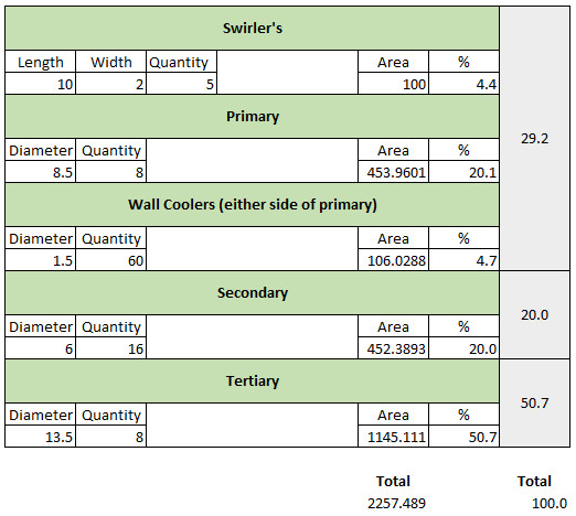 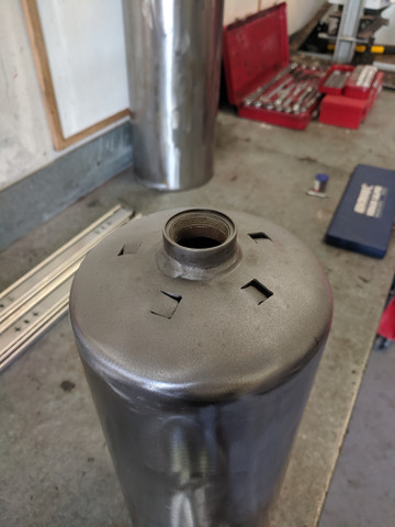 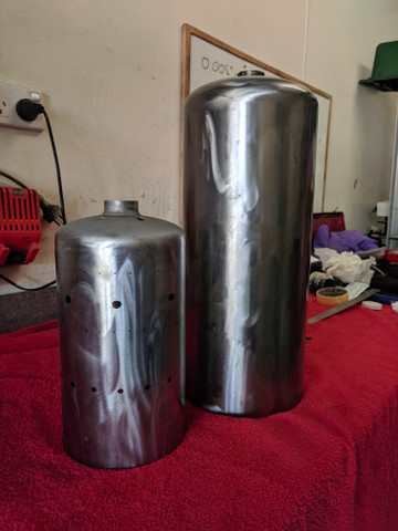
Note - I have not drawn on the tertiary holes as i intend on drilling them into the sheet metal cone which ducts the gasses into the turbine (still researching the best way to create this component). Some goodies rocked up in the mail! 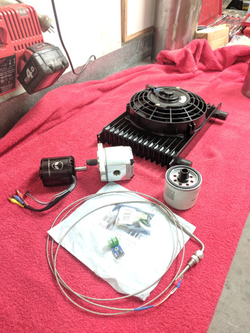 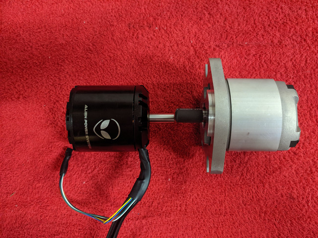 |
|
|
|
Post by cchange4us on Feb 22, 2020 0:19:03 GMT -5
So a few weeks ago a H1C Holset popped up on Gumtree, the price was really good and i decided to purchase it. I did state before that i had forgotten the idea previously however the price was to good to not pick it up. The H1C's are (for this projects purpose) the same, the turbine and compressor are compatible with the HX35's. This one is without a waste gate which makes it easier for when i want to blow some air through a power turbine  I had the chance to melt bits of steal together over the last few weekends. A cone template was used to cut the correct profile of 1.6mm sheet : 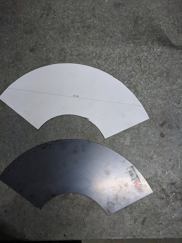 I then finished off the mixing holes: 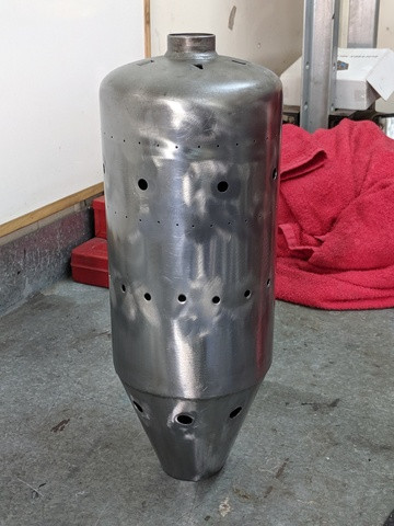 I picked up the profile cut flanges (6mm) and the combustor housing base (10mm) and set about constructing the combustion chamber: 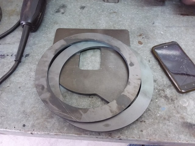 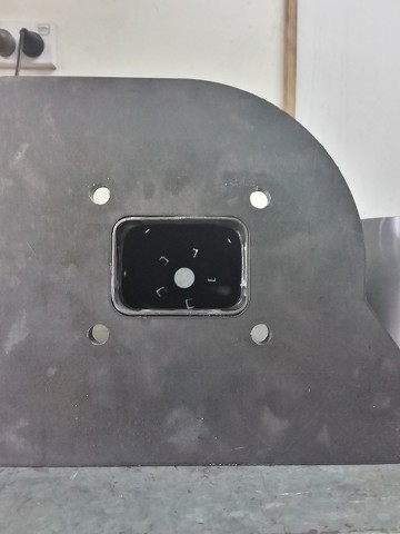
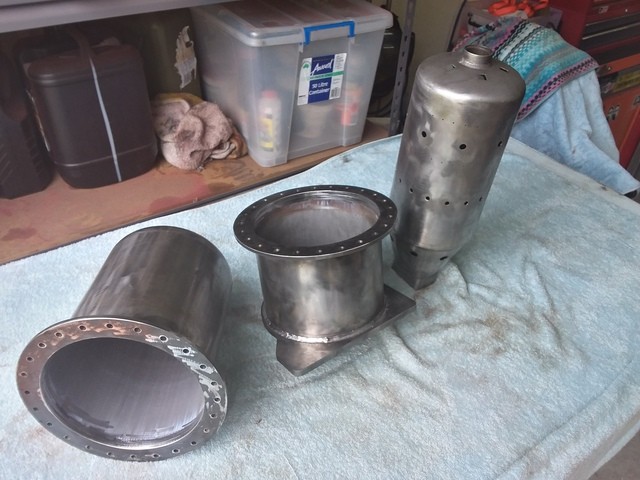 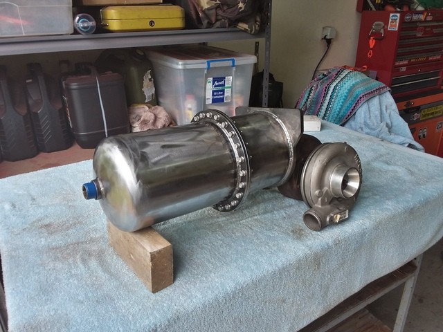 This part of the build was really fun, things started to come together  |
|
|
|
Post by racket on Feb 22, 2020 18:08:30 GMT -5
Very nice job , lotsa small bolts in a flange gives that aerospace look :-)
Cheers
John
|
|
|
|
Post by cchange4us on Feb 22, 2020 22:16:43 GMT -5
Very nice job , lotsa small bolts in a flange gives that aerospace look :-) Cheers John Thanks John, yeah I have always wanted an excuse to go nuts with socket head cap screws and this was my chance 😆 |
|
|
|
Post by pitciblackscotland on Feb 23, 2020 0:29:43 GMT -5
I did the same on my mower project, did you have any warpage in the flanges after welding ?? I did so made up a copper gasket to help with sealing.
|
|
|
|
Post by slittlewing on Feb 23, 2020 13:11:31 GMT -5
Thats some beautiful work. I bow to your fabrication skills!!!
|
|
|
|
Post by cchange4us on Feb 23, 2020 20:04:36 GMT -5
I did the same on my mower project, did you have any warpage in the flanges after welding ?? I did so made up a copper gasket to help with sealing. Yes there was warpage but i consider it to be minimal (i was expecting more considering the amount of heat that went into it). I lightly tacked the two flangers together on the outside perimeter, 50mm apart or so. I kept these flangers together whilst i made the fillet welds that connect the flanges to the pipe. Right before i finished the last weld run some of the tack welds began to pop apart but by then the weldment was well and truly ridgid. There is however one flange section that lifted approximately 0.5-1mm and I think im going to put some sand paper on a pane of glass and flatten the two flanges... two beer job. Thats a good topic, how did the copper gasket go? I thought that i could try some kind of metal crush gasket? but if you had a good outcome with copper i am keen to go with that. Does anyone know how hot this part may get during running? My understanding is that its being hit by radiative heat from the flame tube but also being cooled by the adjescent charge air, so surely not "too" hot? Slittlewing, Thanks  but my work is nothing compared to AusJet on this forum, i actually based my mixing holes and general combustor chamber layout from his build. The bloke knows how to fabricate! |
|
|
|
Post by pitciblackscotland on Feb 23, 2020 23:42:46 GMT -5
I did the same on my mower project, did you have any warpage in the flanges after welding ?? I did so made up a copper gasket to help with sealing. Yes there was warpage but i consider it to be minimal (i was expecting more considering the amount of heat that went into it). I lightly tacked the two flangers together on the outside perimeter, 50mm apart or so. I kept these flangers together whilst i made the fillet welds that connect the flanges to the pipe. Right before i finished the last weld run some of the tack welds began to pop apart but by then the weldment was well and truly ridgid. There is however one flange section that lifted approximately 0.5-1mm and I think im going to put some sand paper on a pane of glass and flatten the two flanges... two beer job. Thats a good topic, how did the copper gasket go? I thought that i could try some kind of metal crush gasket? but if you had a good outcome with copper i am keen to go with that. Does anyone know how hot this part may get during running? My understanding is that its being hit by radiative heat from the flame tube but also being cooled by the adjescent charge air, so surely not "too" hot? Slittlewing, Thanks  but my work is nothing compared to AusJet on this forum, i actually based my mixing holes and general combustor chamber layout from his build. The bloke knows how to fabricate! Just had a look at my old photos of the build, i use ss sheet for a gasket you could also use steel sheet. I never got to test it out as i scrap the project. Cheers, Mark.   |
|
|
|
Post by cchange4us on Apr 4, 2020 5:52:03 GMT -5
Hi All, well! ... Crazy times eh? I have been slowly chipping away at this project. The turbine housing and cast-steel adapter has been port matched to aid flow, this was a fun job - seriously. It was all done with a die grinder and i'm pretty sure i have 3kg worth of metal shavings in my hair right now. Before:  During: 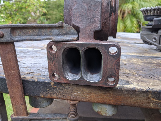 After: (Blue paint for added effect). 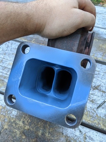 It will be interesting to see if the leading edge of the bridged section erodes away through thermal corrosion, i have heard that this can be an issue... not that i particularly care. I also thought it was a good idea to sand down the combustion chamber flange faces. Even though i was impressed with how little the flanges warped during the welding process, i thought it was still a good idea to sand away a few of the high points to give the (still to come) copper gasket a chance. 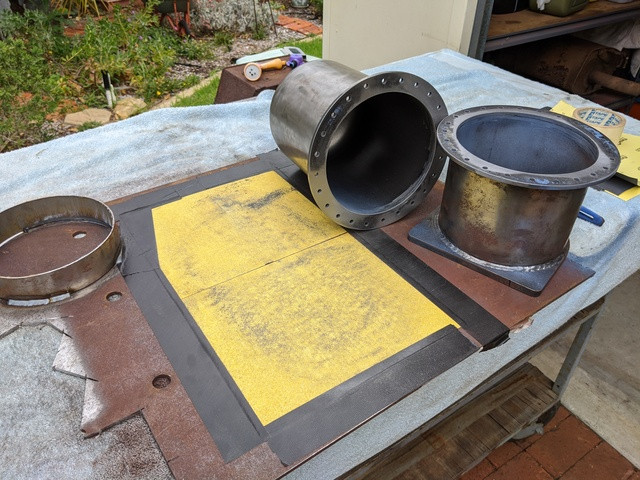 Currently at the profile cutter's is the supporting sheet metal that i have designed to keep this assembly under control. Heat soak into surrounding structures may becomes an issue with this design (due to a direct thermal pathway between the bottom combustor flange and the supporting structure) however i guess we will see! 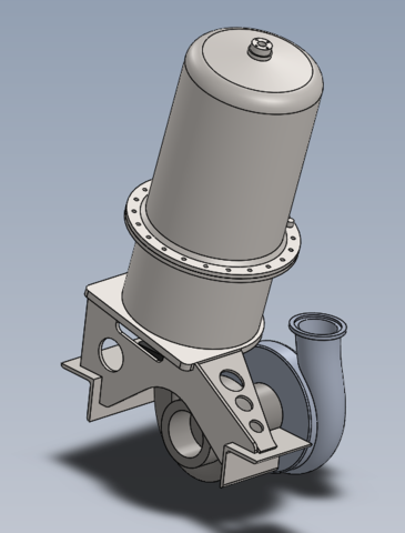 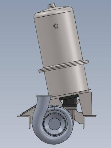 One last thing worth mentioning: I have been trying to think of a simple way to position (and feed) an oil spray nozzle inside the combustion chamber, whilst also allowing for LPG to be injected for startup . I came up with a design and sent it out for a quote at a local machining shop... Since selling my liver is not an option, i am now looking for other ideas that i could build myself -- Has anyone developed a modular system to allow oil injection and an LPG feed for startup? 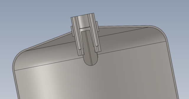 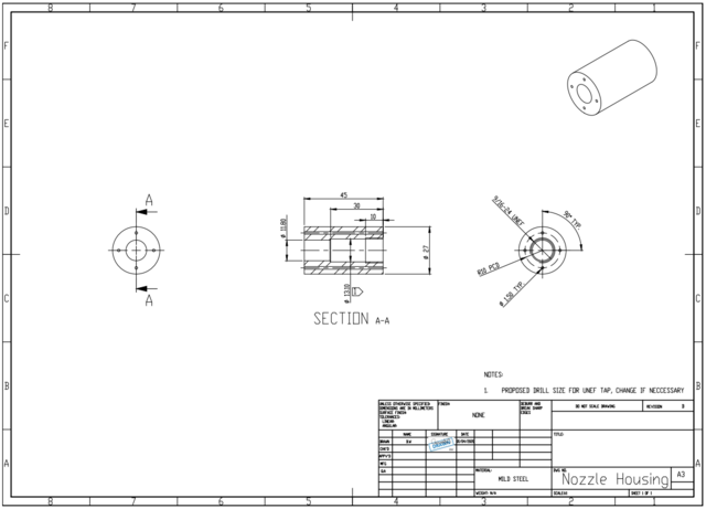 |
|
|
|
Post by racket on Apr 4, 2020 17:15:41 GMT -5
You'll be OK with the turbo mount , I used something similar on my 2 shaft kart jetandturbineowners.proboards.com/attachment/download/53On my TV84 engine the LPG was fed into the area surrounding the fuel nozzle supply and its discharged around the spray nozzle , it can't ignite until air mixes with it so the nozzle stays "cool" |
|
mitch
Senior Member
  
Joined: August 2014
Posts: 285 
|
Post by mitch on Apr 10, 2020 18:39:07 GMT -5
Excellent, look forward to the excel sheet. I agree PWM is the way to go. I did manual PWM control (with a cheap Chinese one) and it worked nicely on my previous fire ups (no regulator or anything). Now am closing the loop with arduino! Efficient as you say, allows for automated low pressure starting, I intend to just keep the target oil pressure about 1 bar above P2. Cheers Scott What are people using for PWM control? I had created a system that used an arduino with a MOSFET, with a 24v dc scooter motor (running on a 12v battery) to control motor/ pump speed. It worked great while the motor was disconnected from the pump, but as soon as the pump put a load on the motor (especially near 0 rpm) the MOSFET would burn out and pop. Sorry if this is a bit off topic from the recent posts! |
|
|
|
Post by racket on Apr 10, 2020 20:05:47 GMT -5
|
|