ashpowers
Veteran Member
  
Joined: February 2011
Posts: 207
|
Post by ashpowers on Sept 5, 2014 15:29:31 GMT -5
I dont think I'd say the air flow is separating - I think the particles it is carrying aren't following the backwall of the vane.
|
|
nersut
Veteran Member
  
Joined: September 2012
Posts: 223
|
Post by nersut on Sept 5, 2014 21:21:18 GMT -5
Hi Chris & Ash I don't have "any" clue on fluid dynamics etc, so I can't really comment your post, but good reading!  I will play with SolidWorks & try the 3D fluid simulator after watching some youtube tutorials  I am a little concerned about the distance between the turbine & NGV which is only 3 mm. Is it going to be a problem? The turbine inducer tip height is 15 mm same as the NGV. 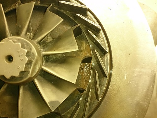 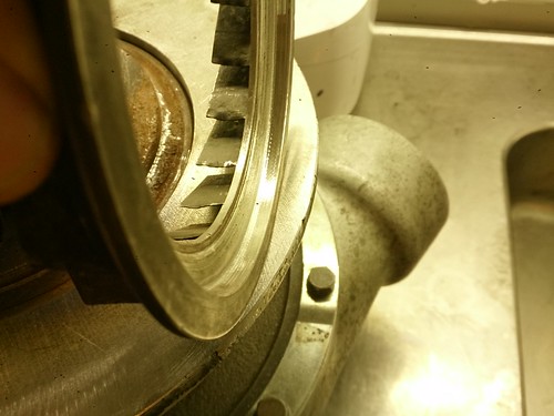 I removed some material from the backside of the NGV to seat it on the turbo flange. The NGV material was very tough & it was hard on the lathe. The trimming is not enough to seat it to level it to the turbine inducer height. I don't want to shave too much material off & make it too weak. 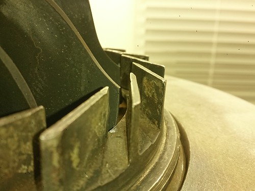 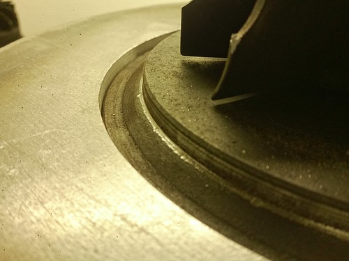 I will have to split the turbo apart & remove the conical part of the cast heat shield to align the height of the turbine & NGV. Cheers Erik |
|
|
|
Post by racket on Sept 5, 2014 22:56:35 GMT -5
Hi Eric
3mm will be fine .
Cheers
John
|
|
nersut
Veteran Member
  
Joined: September 2012
Posts: 223
|
Post by nersut on Sept 6, 2014 11:42:30 GMT -5
Hi Eric 3mm will be fine . Cheers John Hi John Okey thanks. How can I calculate the NGV throat area and see if it fits the compressor size? Cheers Eik |
|
|
|
Post by racket on Sept 6, 2014 17:03:35 GMT -5
Hi Erik
Measure the total throat area of the setup you have and if its between ~16 - 18 sq cms it'll do .
Cheers
John
|
|
nersut
Veteran Member
  
Joined: September 2012
Posts: 223
|
Post by nersut on Sept 6, 2014 23:12:11 GMT -5
Hi Erik Measure the total throat area of the setup you have and if its between ~16 - 18 sq cms it'll do . Cheers John Hi John Ok thank you, if I am not taking mistake about the NGV throat area calculation, it is spot on. 20 vanes/passage ways, 14,5 mm vane height & 6 mm at the narrowest point (red arrow), see picture below. 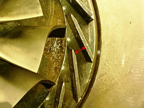 (0.6cm x 1.45 cm) x 20 = 17,4 cm2  --------------------------------- Compressor inducer diameter 74.5 mm = 43,6 cm 2 inducer area 40 % of compressor inducer area = 17,4 cm 2 = NGV throat area.  Please correct me if I am miscalculation the throat area. Cheers Erik |
|
|
|
Post by racket on Sept 7, 2014 1:29:55 GMT -5
Hi Erik
Sounds good to me :-)
I worked it out roughly by using a flow of 1.4 lbs/sec trying to get through a choked "nozzle" at ~1750 ft/sec at 1000 deg K and at a 1.77 PR , the comp turning out a 3:1 PR .
Cheers
John
|
|
|
|
Post by finiteparts on Sept 7, 2014 12:22:29 GMT -5
Erik, What a lucky find! That NGV ring almost looks like it was made for your purposes. I dont think I'd say the air flow is separating - I think the particles it is carrying aren't following the backwall of the vane. Ash, I think that is a good possibility...that's the best part about this site...multiple viewpoints and many shared ideas. Another thought is that there could be many operating conditions included in "where" this occurred...and since we don't know how this was operated, the streaks are at best time averaged flow conditions, so the some streaks could be due to one flow condition and others due to another flow condition. I just thought it looked very similar to the testing that IHI did, even though their testing was on a straight channel diffuser arrangement... it is reported in: "The Experimental Study of Matching Between Centrifugal Compressor Impeller and Diffuser", Tamaki, H., et. al., ASME Journal of Turbomachinery, Jan. 1999, Vol. 121, pp 113- 118. An interesting point from their paper was that the condition where they injected the oil and "saw" the flow separations on the diffuser vane suction side was at their peak operating efficiency points! They were comparing two similar straight channel diffusers out of a set of eleven varied diffuser designs (airfoil, conformally transformed and wedge (or straight channel)). The difference between the two was the length of the wedge after the throat section, which cause them to experience different extents of flow separation, but even with that, they experienced very similar pressure recovery performance. ~ Chris |
|
ashpowers
Veteran Member
  
Joined: February 2011
Posts: 207
|
Post by ashpowers on Sept 8, 2014 14:50:42 GMT -5
One idea that would work is to make your diffuser cover from clear polycarbonate. A small "streamer" could be attached to the backwall of a vane and its behavior observed. Flow separation will be easy to see in that case.  Or a more practical method would be to install a quartz viewing window into the diffuser cover. But, I would be more inclined to model the part in SW and run a flow analysis on it. From my experience with flow simulation in SW, it is pretty much on the money so long as you have all of the conditions properly configured. I've designed parts (for my business) with it, had them 3d printed, and took them to the flowbench to check the results to the simulations. They have been spot on each time. -Ash |
|
nersut
Veteran Member
  
Joined: September 2012
Posts: 223
|
Post by nersut on Sept 10, 2014 21:32:17 GMT -5
Small update Heat shield trimmed. I had no access to a lathe at the moment, so I decided to trim the cast turbo heat shield with a Dremel.  It took me over 3 hours & 5-6 grinding wheels to shave metal off to align the turbine with the NGV, the plus side is I didn't have to take the turbo apart. 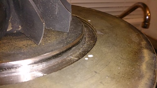 I am currently sourcing different stainless steel parts for the annular combustor, cooking pots with nice curves etc.  Cheers Erik |
|
nersut
Veteran Member
  
Joined: September 2012
Posts: 223
|
Post by nersut on Dec 3, 2014 15:18:47 GMT -5
Hi everyone!
I have a quick questions about power turbine bearing housing.
It is possible to use a regular (brass bushing) turbo center cartridge, remove the compressor wheel & instead mount a chain sprocket or a spur gear?
How well (or bad) will the oil pressure/film in the cartridge be able to handle the radial loads from a chain sprocket/spur gear?
Cheers
Erik
|
|
nersut
Veteran Member
  
Joined: September 2012
Posts: 223
|
Post by nersut on Dec 3, 2014 15:27:38 GMT -5
New additions to my turbo collection  A couple of Cummins ST50's 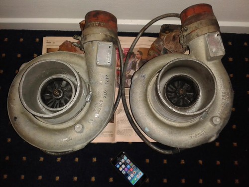 Cheers Erik |
|
|
|
Post by racket on Dec 3, 2014 16:21:22 GMT -5
Hi Eric
All you'll need to do is fit a sealed ball bearing in an outboard position from the sprocket to take radial loads , whilst still retaining the "bush" inside for the usual turbo loads , because you're chain drive will limit rpm of the freepower the sealed bearing will function OK .
Cheers
John
|
|
nersut
Veteran Member
  
Joined: September 2012
Posts: 223
|
Post by nersut on Dec 3, 2014 16:30:30 GMT -5
Hi Eric All you'll need to do is fit a sealed ball bearing in an outboard position from the sprocket to take radial loads , whilst still retaining the "bush" inside for the usual turbo loads , because you're chain drive will limit rpm of the freepower the sealed bearing will function OK . Cheers John Thank you again John, quick respons  Which size/no. chain is recommended for high rpm use? Cheers Erik |
|
|
|
Post by racket on Dec 3, 2014 23:12:44 GMT -5
Hi Erik
I'd go for the best quality #35 kart racing chain you can find , 15,000 rpm is a reasonable figure though, I did rev some to 22,000 "engine??" rpm with a 10 teeth engine sprocket once , its probably got the "best??" rpm vs power transmission capability for direct drive for a turbine build as it can be made any length and joined together ..................should be able to handle 30 hp easily .
Cheers
John
|
|