|
|
Post by stoffe64 on Apr 18, 2013 4:20:52 GMT -5
hello again!
that new turbo you have,does it has a bigger turbine wheel than the old one?,that can cause some troble also, you better check it out,turb wheel should be about 25% bigger than comp wheel
cheers/stephan
|
|
nersut
Veteran Member
  
Joined: September 2012
Posts: 223
|
Post by nersut on Apr 18, 2013 4:31:08 GMT -5
Hi Stephan!
The new turbo is identical to the old one, same size. (but a newer version)
The old had Garrett p/n: 466074-9001 Volvo/Garrett TA5101
And the the new one has: 466074-9011 Volvo/Garrett TA5101
Cheers!
Erik
|
|
|
|
Post by stoffe64 on Apr 18, 2013 5:05:34 GMT -5
ok,then it should be fine if it is the same wheel sizes;)
cheers/stephan
|
|
nersut
Veteran Member
  
Joined: September 2012
Posts: 223
|
Post by nersut on Apr 18, 2013 22:48:11 GMT -5
Hi everybody
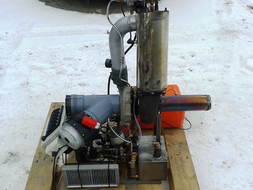
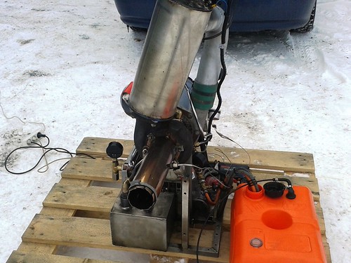
I am planning to make my turbine more compact.
I will relocate the fuel pump & ignitor and mount them on the combustor can.
My current oil system is big, heavy, bulky and draws a lot of current ( 220v electric drill/power steering pump)
1. Can I use a Bosch 044 fuel pump as a oil pump?
Pros: very compact, less current draw, 12v, up to 5 bar pressure.
Cons???
2. Can I use a fuel pressure regulator to regulate oil pressure?
Cheers
Erik
|
|
|
|
Post by finiteparts on Apr 18, 2013 23:05:22 GMT -5
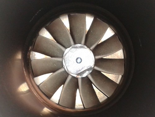
First off, nice engine...Thanks for sharing! The pictures of the damage to your turbine wheel appears to be due to over-stressing the wheel. I have a TPE-331 turbine wheel that suffered a hot start and it lost a bunch of chunks out of the blade tips. Over-stressing is a combination of centrifugal force and temperature. The ultimate tensile strength of the metal drops as temperature goes up and since the centrifugal force is a function of radius, the tips usually go first. The stress cracks running near the tip support this. Did you see any flame in the turbine wheel or a glow when running? Since type k thermocouples are capable up to 2500F (see Omega Engineering for specs) and the inlet temperature capability of inconel 713C or GMR 235 is around 1700F there should be no reason to worry about them melting. I think the EGT probe (assuming it is a type k or better) should be upstream of the turbine wheel that way you can make sure that you don't over-temp the wheel as opposed to downstream. Or even better, have both, that way you can calculate the work done by the turbine more accurately. The swirl pattern you have on the liner is due to the fact that you have the combustor inlet offset. Usually, it is desirable to have the flow field around the liner as even as possible since this allows an even static pressure feed for all the liner dilution holes. With a swirling inlet air, the static pressure variation could be causing a skewed air/fuel distribution. Some of the Garrett GTC/P-85 APUs have a "shield" to keep the air discharging from the diffuser near the combustor from locally overfeeding the closest air holes...just an idea...   |
|
|
|
Post by racket on Apr 19, 2013 0:54:33 GMT -5
Hi Erik
The combustor can gets pretty hot at higher pressure ratios , I've measured a T2 of 250 C , temps of 150 C would not be uncommon even at more modest P2s , not the sort of temp you want feeding into your fuel pump or ignitor .
Fuel pumps aren't meant to be used as lube pumps , the ones I've tried don't even like pumping thin oil .
Cheers
John
|
|
|
|
Post by racket on Apr 19, 2013 1:06:15 GMT -5
Hi Chris
GMR235 is a lower temp material best used for diesel turbos with a TIT of up to 850 C , Inco 713 can go to 1050 C .
Our turbo turbines can throw turb tips at "safe? " temperatures if the engine goes into surge , the gyrations of the turbine wheel simply throws them off .
Cheers
John
|
|
nersut
Veteran Member
  
Joined: September 2012
Posts: 223
|
Post by nersut on Apr 20, 2013 20:18:37 GMT -5
Hi 'finiteparts' & John Yes, a lot of bad things happened in just seconds, probably a combination of low/no oil pressure, bearing failure, overheat, surge and more...  But the good news is that my turbine runs nicely again!  I test run it 5 times today with no problems at all. Good oil pressure (4.5bar), stable P2 pressure & EGT temperature.   Here are some data from today's test run. | Fuel pressure (bar) | P2 pressure (bar) | EGT temperature (celsius) | | 6 | 0.6 | 410 | | 8 | 1.0 | 450 | | 10 | 1.3 | 520 | | 12 | 1.5 | 570 | | 13 | 1.6 | 610 |
I think that my fuel pump is maxed out at 13 bar with 0.5gph + 9.5gph nozzles, but I am close to max "safe" EGT temperature of 650 degrees Celsius. Maybe I should try to tapper the jet nozzle more by small amounts to get EGT temperature of 650 degrees Celsius & a higher P2 pressure...? I modified my starter motor & made it more compact. The turbine starts nice & easy with strait diesel fuel & a sparkplug at outside temperature of minus 10 degrees Celsius  My ignition coil is mounted on top of the combustor can with a bracket, it doesn't get warm at all. I think I will weld a bracket for the fuel pump on the air delivery tube and keep about 5 cm distance from the combustor & the air tube. Then my fuel pump shouldn't get warm, I think.  The turbine wheel looks very clean & have a uniform color after todays test runs.  The end cap is still leaking some air & a little oil leak from the oil return flange, should be easy fix. And I will try to find a 12V gear oil pump, any recommendations? Cheers! Erik |
|
|
|
Post by racket on Apr 20, 2013 22:42:54 GMT -5
Hi Erik
Theres something not making sense here :-(
Assuming a 11 bar pressure drop across your spray nozzle , it should flow ~28% more than the calibrated flow at 100psi . .................but with a ~64mm comp inducer the airflow should be ~1 lb/sec so fuel flow ~60 lbs/hr or 8.5 gph required , but it sounds like you've got ~50% more fuel flowing .
You WON'T get a higher P2 by tapering your jet nozzle and making the flow area smaller , all that will happen is your temperatures will increase , to get more P2 you need more fuel and perhaps a slight increase in nozzle diameter to flow the increased mass flow at the higher rpm
Definitely fix any leakage at the end cap as that will be increasing your TOTs as the turb stage
works with less mass flow than the compressor .
With minus 10 C ambiant temps your mass flow will be considerably higher ( >10%) than a comp map would suggest, and the lower temp will mean you'll produce a higher P2 for a certain rpm , ..................excellent temps for running a turbine engine :-)
What diameter is your jet nozzle ??
Cheers
John
|
|
|
|
Post by stoffe64 on Apr 21, 2013 2:00:56 GMT -5
hello Erik!
search for PIUSI VISCOMAT 12V PUMPS
|
|
|
|
Post by finiteparts on Apr 21, 2013 11:58:57 GMT -5
Hi John and Erik,
I apologize for putting up a "rule of thumb" number...thanks for catching that John! I think the main point of that statement was that the capability of good quality type K thermocouples is well above the maximum turbine inlet temperature, so installing the thermocouple upstream of the turbine gives the user a better understanding of turbine operating environmental conditions. Since the TOT is a function of the work being done through the turbine stage, it carries with it some uncertainty. Aircraft engines can't use turbine inlet temperature (TIT) thermocouples in the higher pressure stages since their firing temperatures are much higher that the 2500 F capability of the thermocouples. Has anyone on here tried to use both upstream and downstream thermocouples? I will on my next engine...
John, I think we are saying the same thing on the turbine throwing off bits...the mechanism can be due to temperature or rotor speed or a combination of both. Holding the inlet temperature constant, increasing the rotor speed can produce a centrifugal stress that exceeded the current material tensile strength...or holding the rotor speed constant, increasing the temperature can reduce the tensile strength capability below the current level of centrifugal stress. So without having gauges (tach, EGT (or TIT), P2, etc) you can't say.
Erik, you said that there might have been a reduction of oil flow, so that would easily cause excessive rotor drag.
"Our turbo turbines can throw turb tips at "safe? " temperatures if the engine goes into surge , the gyrations of the turbine wheel simply throws them off . " - John, I have never heard about this phenomenon...on aircraft engines, the problem with surge is the reduced airflow from the compressor during the reduced section of the surge cycle. Also the loss in airflow and the delayed response of the fuel system leads to very rich fuel air conditions...this can lead to either very high flame temperatures or the continuation of the burning into the turbine section. Both of these lead to excessive turbine surface temperatures. The inertia of the rotor system is such that the rpms/centrifugal loads are much slower to change and thus with the higher turbine entry temperatures, the turbine metal capabilities are exceeded and chunks start coming off.
Do you have any info on the mechanism of this phenomenon? Maybe when you are getting to surge, you are exciting a vibrational mode at the turbine tips?
I had one of my turbo engines go into a severe rub when I let the turbine oil temperature go really high. I now have learned in my rotordynamics research that the oil viscosity plays a huge roll in the bearing "stiffness" and damping. Bearing stiffness and damping control the response of the system to vibrational forcing functions (out of balance, gravity, pulsing flow from the combustor, aerodynamic cross-coupling, etc). For the floating bearings, this leads to movement of the rotor centerline away from the bearings/housing centerlines. Hydrodynamics bearings often suffer from conditions known as oil whip or whirl that I think caused the severe rub event. It was so bad that I was able to see the compressor nut whirling around (more like a cloud of blurred compressor nut).
|
|
|
|
Post by racket on Apr 21, 2013 19:04:40 GMT -5
Hi Chris
We generally recommend a "downstream" position for thermocouples to prevent anything going through the turbine wheel , our DIY world is a little less regulated than the aero one .
The throwing of turbine tips was something that was quite common back in the 1970-80s when guys first started putting earthmoving turbos on auto engines , the "oversized" turbo often went into surge and the turb tips were "thrown" , I threw tips on my TV84 turbo (the turbo used in my first turbine bike) back in the development stages when I sent it into surge , the overhaul guys then told me about how it happened in those early days...................the wheels were neither overtemp'ed or oversped , but they lost tips.
Cheers
John
|
|
nersut
Veteran Member
  
Joined: September 2012
Posts: 223
|
Post by nersut on Apr 21, 2013 22:01:56 GMT -5
Hi John, Stephan & 'finiteparts' Thank you for your good inputs!  I used exhaust gasket (metal/"lead"-type) at the end cap, maybe not the right stuff? I could try with regular flange gasket, the lime green type if it can withstand heat. I hope that it will make a proper sealing, so the turbine can run with more P2 pressure & lower EGT.  The high fuel consumption is confusing... I will post new test data after replacing the end cap gasket. The jet nozzle is about 80 mm. Stephan; I looked at the 12V Piusi oil pump specs. It says max 70 degree Celsius & 30 min. duty/20 min. off... Better alternatives? Does anyone have specs for the Garrett TA5101 turbocharger? Like max pressure ratio or even better a compressor map? Cheers Erik |
|
|
|
Post by racket on Apr 22, 2013 0:03:31 GMT -5
Hi Erik
You might need more end cap bolts , theres a fair air pressure load on the cap , you could try a silicone sealant , once its cured/set it should stop the leaks , but you'll probably need to chisel the cap off when you need to break the seal :-)
80 mm jetnozzle with a 64 comp inducer , thats a relatively large nozzle and should be producing lower temperatures than you're experiencing ......................mmmm, how big is your turbine stage , it could be allowing the comp to flow in the choke region at low efficiencies making your turbine work hard and would account for the temps with that large nozzle opening , also the seemingly high fuel burn rate .
If you are flowing in the choke region you may be already getting near max tip speed even though the pressure is relatively low .
Unless you know the rpm of the engine a comp map will be kinda useless , one thing you could measure is your T2 (temp out of comp) at your 1.6 bar P2 - 2.6 PR , at a 2.6PR and minus 10 C ambiant , your T2 should be ~105 deg C or a tad lower if flowing at best efficiency , but if at ~130 deg C you know you're flowing in the choke region and is the reason why things are as they are .
Hope this helps :-)
Cheers
John
|
|
nersut
Veteran Member
  
Joined: September 2012
Posts: 223
|
Post by nersut on Apr 22, 2013 2:38:27 GMT -5
Hi John I am planning to add more end cap bolt. But I could try with high temp silicone sealant first. The turbine wheel size is: 77.7 mm & 88.9 mm. Ok, I will mount a T2 temp gauge. I ordered a laser RPM-meter from eBay months ago, but it never arrived...  Cheers! Erik |
|