nersut
Veteran Member
  
Joined: September 2012
Posts: 223
|
Post by nersut on Nov 2, 2012 2:38:14 GMT -5
Hi John
I haven't test the axial play yet, I will do that tomorrow. Fingers crossed.
Oh, I forgot to mention that I made some slits on the tube/jet nozzle & made it taper a little.
I haven't test the fuel flow correctly. I used the data from the nozzle & some simple calculations.
Cheers
Erik
|
|
|
|
Post by racket on Nov 2, 2012 14:33:23 GMT -5
Hi Erik
So what diameter is your jetnozzle compared to the comp wheel inducer ??
You could have gone into surge which can cause large rotor gyrations which can cause a comp rub ..................and in a worse case scenario bend the rotor shaft , I'd suggest you give the rotor a spin by hand to make sure the shaft hasn't bent .
I noticed you have a fluid filled P2 gauge , not a good idea as the damping effects of the fluid will mask any P2 fluctuations associated with surge , we need a P2 gauge that has no damping either fluid or inlet restrictors .
Hopefully your comp rub hasn't been too severe and the turbo is still useable .
Cheers
John
|
|
nersut
Veteran Member
  
Joined: September 2012
Posts: 223
|
Post by nersut on Nov 2, 2012 19:06:05 GMT -5
Hi John The tube is 89 mm, same size as the turbine outlet. And at the jet nozzle outlet is about 80 mm. The compressor wheel inducer is 64.25 mm & the exducer is 91 mm. My P2 pressure gauge is not fluid filled, it is a simple gauge with a plastic "glass". I think the Garrett TA5101 is not optimal for DIY gas turbine use. The compressor is similar to a GT42 & the turbine is similar to a GT45. So the turbine part must be over-sized. I don't think that the shaft is bent & the compressor wheel looks still ok. But the side-to-side movement is too much. The axial play is minimal about 0.5 mm. I ordered a service/rebuild kit from a company called " Esbjerg cylinder service" in Denmark for about 100 bucks. The turbo is old & was taken from a 1970's Volvo N12 like this one: 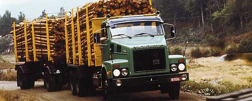 The turbo is older than me!  So a service kit is more that welcome! ;D Could you remind me how to do a compressor surge test? I read it somewhere but I don't remember the "how-to-do" steps, something with a strip at the intake.  Cheers Erik |
|
|
|
Post by racket on Nov 2, 2012 22:48:23 GMT -5
Hi Erik
Mmmm,.......... with that sized jet nozzle there shouldn't be a problem with surge , but its easy to check by installing a piece of lightweight string/thread at the comp inlet so that the end of the string can't quite touch the comp inducer when pulled tightly , make sure the string is securely fastened as the inlet suction will do its best to ingest it . ...................if theres no reversal of flow (surge) during operation then the string should simply assume the streamline of the air entering the comp wheel , but if there is surge then the string will be bouncing in and out with the air flow .
That good news about your P2 gauge being unfilled and hopefully with no inlet restrictor, I assumed it was filled from looking at the pic in the vid , my apologies .
With 0.5mm of axial play it sounds like the thrust bearing has failed as there should be minimal in and out play , with regard radial play , the comp shouldn't be able to touch the housing if forced from side to side .
If your thrust bearing failed and the shaft moved forward and the comp wheel has touched the housing, the resulting gyrations probably have caused the radial rubbing , hopefully the compressor wheel isn't wrecked when you remove the housing .
$100 for a service kit is a good price , I hope it fixes your problems :-)
Cheers
John
|
|
nersut
Veteran Member
  
Joined: September 2012
Posts: 223
|
Post by nersut on Nov 4, 2012 16:18:27 GMT -5
Hi John Thanks for the information. When the gas turbine runs there is no fluttering sounds at all, just clean uniform compressor whine. But when I look closely at the P2 pressure gauge it bounces a little pretty fast.. by maybe max 0.1 bar. Could it be surging or could it just be air turbulence? The P2 pressure gauge has no restrictor & is installed on the compressor discharge line & not on the combustor it self. Maybe I should relocate the gauge to get a more accurate & stable reading? When the service kit arrives & installed & IF the turbo is not dead I will do some more testing & hopefully the laser tachometer would have arrived too. I will note: - N1 rpm
- P2 pressure
- TOT temperature
- Thrust reading
- Actual fuel consumption
Cheers Erik |
|
|
|
Post by racket on Nov 4, 2012 20:38:11 GMT -5
Hi Erik
The slight fluttering could be turbulence near your pickup point and/or "normal" combustion instability, 0.1 bar fluctuation isn't a problem , ................a pickup point where the air is moving slower is a better proposition , somewhere in a corner of the outer can well away from the delivery tube and its high speed airflow .
Hopefully the kit arrives quickly and everything goes back together without a problem :-)
Cheers
John
|
|
nersut
Veteran Member
  
Joined: September 2012
Posts: 223
|
Post by nersut on Nov 4, 2012 20:43:15 GMT -5
I am thinking about using a IC ECU to control my FJK-2. I have a MegaSquirt fully programmable ECU I used earlier to convert my old carburated Volvo 245 2.3L to EFI with great succes. I also installed a camshaft from a Volvo-Penta boat engine to the car, much bigger valve lift & longer durations. The MegaSquirt ECU has a builtin 1.5 bar MAP sensor.
Have anyone tried to port IC ECU to gas turbine use?
Cheers
Erik
|
|
nersut
Veteran Member
  
Joined: September 2012
Posts: 223
|
Post by nersut on Nov 4, 2012 20:53:47 GMT -5
Hi John
Ok.
I will relocate the P2 gauge to the combustor outer can, seems to be a good idea.
Cheers
Erik
|
|
nersut
Veteran Member
  
Joined: September 2012
Posts: 223
|
Post by nersut on Nov 9, 2012 2:35:02 GMT -5
Update I received my new Allison Rolls Royce 250, 3rd Turbine Wheel from eBay  It looks very cool & in good condition! Wheel diameter about 190 mm. Blade height about 32 mm 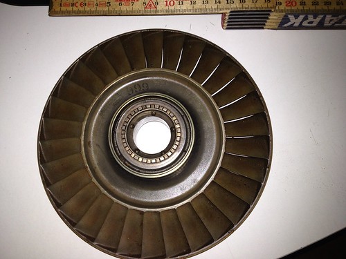 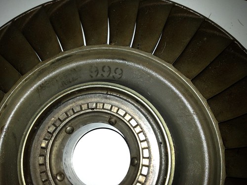 I am still waiting for the service kit for my Garrett TA51 turbocharger. ________________________________________________ Hi John I have a quick question for you  Could I make the nozzle guide go 360 degree by making the flow area smaller instead of the half-moon design? 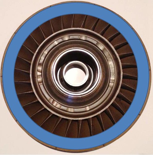 Flow area marked in blue 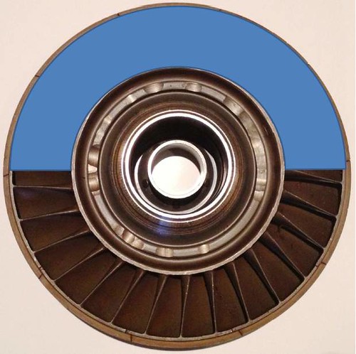 Flow area marked in blue And do you know what the 999 stamped on the turbine wheel means? Cheers Erik |
|
|
|
Post by racket on Nov 9, 2012 3:15:58 GMT -5
Hi Erik
The 999 is probably 9.99 square inches , this is the flow area of the turbine wheel's outlet between the blades .
The inlet flow area will need to be determined after your gas producer is fully developed , but considering I used a turbo with a 3.5" dia inducer feeding the full annulus of my third stage wheel you'll only be needing partial entry as per your last pic .
If you used the full 360 degree entry your gases will slow down once they enter the large flow area within the wheel and not re accelerate as they should in a reaction wheel .
You might get away with full 360 degree entry if it was at the blade roots rather than the tips as the root area is fed higher velocity gases from the NGV and acts as an impulse turbine wheel where full pressure drop is within the NGV .
My choice would be a segment entry as the extra surface area of the full entry ducting would probably increase losses substantially .
Cheers
John
|
|
wolfdragon
Senior Member
  
Joined: April 2011
Posts: 287
|
Post by wolfdragon on Nov 9, 2012 8:13:56 GMT -5
Why not make a plate that completely blocks X number of paths and leaves the rest wide open? I'm sure some sort of pattern would emerge and look interesting...
Or would this cause thermal shocking issues on the reaction wheel?
|
|
Eben
New Member

Joined: September 2010
Posts: 6
|
Post by Eben on Nov 9, 2012 20:47:35 GMT -5
Yes, if you are trying to evenly distribute the blocked and open ports/paths around the radius, I am sure it will be fairly easy to come up with a, hopefully, "balanced"or symmetrical pattern.
But, do please consider the possibility that you may induce additional "drag" (counter-pressure / resistance to flow) as a result of excessive turbulence between "flowing" and "stagnant" areas/stages/ports/paths of the annulus. (i.e. shear caused by/resultant from laminar, turbulent, transient flows)
Maybe another confuguration would be more efficient, maybe?
|
|
|
|
Post by racket on Nov 10, 2012 2:43:07 GMT -5
I think it boils down to whats the easiest to make as well as giving the least losses and the most power , none of the proposed methods is ideal .
Making several evenly spaced nozzles would be a better way to go but it entails some large construction hurdles to overcome .
Its very early days with this build , wait until the gas producer is fully developed before worrying too much about freepowers .
Cheers
John
|
|
|
|
Post by stoffe64 on Dec 18, 2012 13:11:04 GMT -5
hello,just checking of the progress on your project, very curious to see more of your engine!
cheers/stephan
|
|
nersut
Veteran Member
  
Joined: September 2012
Posts: 223
|
Post by nersut on Apr 18, 2013 4:12:26 GMT -5
Hi folks! I have been busy, I started my own business & didn't have time to work on the turbine. I have finally disassembled my turbine today. I found that the turbine wheel was melted...  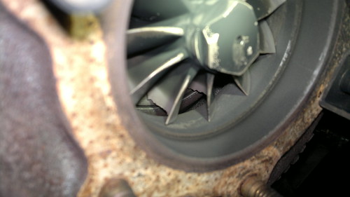 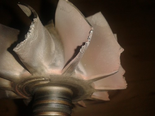 It must have happened when the compressor wheel began to rub the housing because of worn journal bearings & failed thrust bearing. I was lucky to find another Garrett TA5101 turbo & got it for free  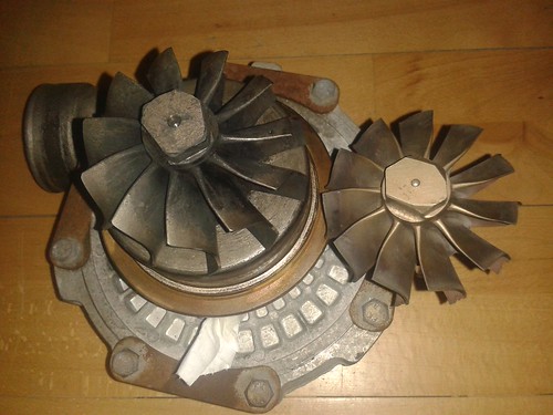 Here is the new donor turbo next to the melted turbine wheel. I cleaned the new turbo & installed it to the frame. 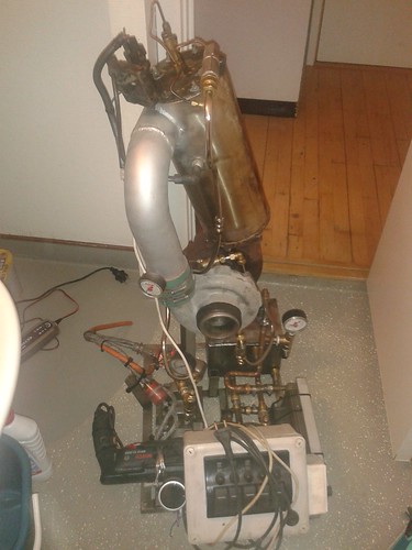 The turbine is almost ready to be tested  New name for the turbine, FJK-2B ;D Cheers! Erik |
|