|
|
Post by britishrocket on Apr 1, 2012 3:48:06 GMT -5
Hello Anders,
Hi, I thought the ignition would be something like that and I think it will work just fine. I also think you are right to go with the water cooling. Far safer and you will find out if regen cooling is possible and to what extent.
I used pulse TIG when welding my combustion chamber as I had a relatively massive flange next to a thin wall. I was worried about thermal run away and the wall melting. I didn't want a lot of patient work on the lathe ending up in a big melted mess! You can read about this on my blog under "Welding the Combustion Chamber".
Best Wishes,
Carl.
|
|
|
|
Post by Johansson on Apr 1, 2012 13:32:42 GMT -5
Hi Carl, (good to have a name since saying Hi Brittish Rocket Research would feel a bit awkward)  As long as the ignition occurs far up the thrust chamber I think I will be fine, first I thought about using a torch ignitor to ignite the NOX/methanol mix after it had passed through the nozzle but that would cause a massive combustion pressure peak that most likely would damage the aluminum thrust chamber. This engine will be somewhat of a test engine, the injector is pretty crude which forces me to make the TC overly long for complete combustion to occur before the nozzle. When I find out how the "special" features (cheramic coating, all aluminum chamber and water cooling) work I can start drawing up an improved version. If the aluminum chamber survives I am tempted to try to cast a complete TC in one piece instead of having a separate chamber and nozzle welded together, this way I can make the wall thickness more constant since I won´t have to take the joint into consideration. A rocket propelled drop tank racer would be sweet to build some day, a valved pulsejet to push it the first kilometer where a 3000N bipropellant engine takes over.  Cheers! /Anders |
|
|
|
Post by britishrocket on Apr 2, 2012 4:15:35 GMT -5
Hi Anders,
I am in much the same position. That is why my chamber, injector and nozzle have flanges and can be bolted together. That way they can be replaced or changed easily. I have been doing a lot of work to try to discover what characteristics influence injection quality. I see the injector as the heart of the system. It influences all the key performance arbiters of Combustion, stability and Heat Transfer (and hence cooling). If I can get the injector right then everything else should follow.
A cast chamber sounds interesting, I think there is something similar in Sutton Edition 2, I will check the reference later and let you have it so that when you get your book you can check it out.
A rocket propelled racer would be something to see, it would be an amazing ride!
Best Wishes,
Carl.
|
|
|
|
Post by britishrocket on Apr 2, 2012 9:53:37 GMT -5
Hello again Anders,
As promised. On page 187 of Sutton there is a picture of something resembling your cast thrust chamber idea.
Best Wishes,
Carl.
|
|
|
|
Post by britishrocket on Apr 2, 2012 9:55:07 GMT -5
Hi Anders,
For you and anyone else here that is the second edition of Sutton. I really must remember to include all the information in these posts...
Carl.
|
|
|
|
Post by Johansson on Apr 2, 2012 13:46:32 GMT -5
I totally agree that the injector is the heart of the rocket engine, I would prefer to have made a shower head style injector plate with several triplet injectors that produce a more even combustable mist than the simple single triplet injector I use now.
I can design the next engine so I have stainless injector discs that can be easily changed without having to machine a completely new injector head, and with the somewhat crude but functional injector test rig I built I can test plenty of different injection patterns to find one that produce an acceptable spray.
Casting is probably what I will use to make the next thrust chamber, I have been gathering parts for a while now to make a home foundry and have bought green sand and built a pair of flasks so all I need is something that needs casting so I can find inspiration to finish the foundry.
Thanks for the information about the Sutton book, I´ll look it up as soon as I get the book.
Cheers!
/Anders
|
|
wolfdragon
Senior Member
  
Joined: April 2011
Posts: 287
|
Post by wolfdragon on Apr 2, 2012 16:11:46 GMT -5
Anders,
Have you looked into a replaceable nozzle for your next one as well?
If you make it out of graphite, it should hold up to the temperatures, but of it's replaceable, who cares?
|
|
|
|
Post by Johansson on Apr 2, 2012 22:55:06 GMT -5
I´d rather make sure the nozzle survives and make the entire thrust chamber in one piece, adding flanges only complicates things and adds to the list of things that can cause a problem.
|
|
|
|
Post by Johansson on Apr 4, 2012 15:59:55 GMT -5
Today I changed the hydraulic couplings on the cooling jacket to 1/2" hose fittings that I made on the lathe, earlier I bought a pair of fancy (and expensive of course) 1/2" fittings but to my surprise I found out that they was made of brass when I was cutting away the threads...  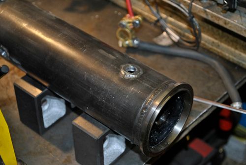 Here the new fittings are in place, they will allow a much higher flow of cooling fluid than before. 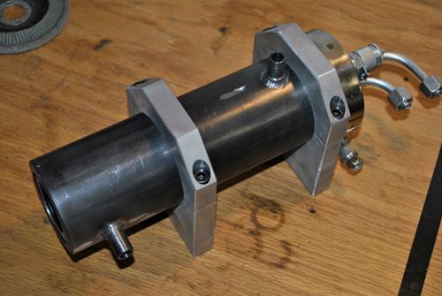 I got a letter about a shipment arriving tomorrow, hopefully it is the 1/4" hydraulic ball valves I´ve been waiting for.  Cheers! /Anders |
|
|
|
Post by Johansson on Apr 6, 2012 16:21:19 GMT -5
That damn shipping company didn´t bother to deliver the package before the holiday so I will have to wait until tuesday to get it.  Anyway, I started to build the test stand for the engine, propellant tanks and water supply tank today. A length of 70X70 steel beam will be used as the main structure. 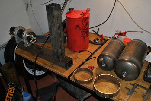 I started by making the propellant tank mounts, I cut two rings out of the same steel tube as the tanks were made of and welded a pair of drilled L-profile beams (might be a better word for them than beam, my technical english isn´t that good) to the ends to act as clamps. 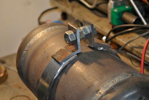 A pic of the finished weld, if only I could lay decent aluminum welds as well... 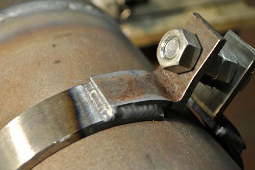 The two tanks with finished mounts cooling off after being welded. 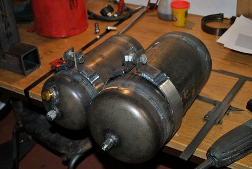 Cheers! /Anders |
|
wolfdragon
Senior Member
  
Joined: April 2011
Posts: 287
|
Post by wolfdragon on Apr 6, 2012 22:53:17 GMT -5
Anders,
It takes a hell of a lot more practice to make aluminum look as pretty as your steel welds. I cheat with my machine and use pure argon with a pointed ceria (orange tungsten) on 150Hz AC with the balance at 70-75% balance so I don't lose the point. But if you don't have an inverter type TIG box, it makes it harder to get that high freq (which makes it TONS easier)
If you have a rectifier type (old style, bigger heavy thing with lots of iron in it) TIG box, provided you are using about >5mm thick AL, you can use DC+ pointed tungsten (any type will do) and pure HELIUM, the lets you break all the "rules" and AL will be as easy to weld as steel. The catch is that with the pure helium, your arc is WAY hotter, so you will just blow through thin material...
|
|
|
|
Post by Johansson on Apr 6, 2012 23:22:22 GMT -5
I have a 160A inverter TIG, the biggest problem is that I don´t like wasting gas and material laying countless meters of test welds so the only practice I get is when I weld on "important" parts... If I had a foot pedal things would get a lot easier since I could control the heat while welding, but more practice is probably what the doctor would order.  |
|
|
|
Post by britishrocket on Apr 7, 2012 16:00:06 GMT -5
Hello Anders,
Very nice work, tidy and neat welds on the mounting brackets. What you called "L profile beam" is usually simply called "angle" in English.
I have run a simulation of the ethanol/liquid nitrous oxide propellant combination using the RPA analysis software. I thought you might be interested in the results.
I don't know anything about your nozzle geometry so I started with the assumption of 300psi chamber pressure (20 bar). This should be about right for these propellants, but of course depends on your nozzle. I also assumed expansion to atmospheric pressure of 14.7psi (1 bar) Assuming a Cp/Cv value of 1.2, this gives a value for Ae/At of about 3.6. This is the figure I used in the nozzle model.
The results were as follows:-
Optimum O/F ratio = 4.7
Cf = 1.39
Cp/Cv = 1.16
Molecular weight of combustion products = 26.3
Chamber gas temperature = 2724.6 degrees celsius
Throat gas temperature = 2553.45 degrees celsius
Exit gas temperature = 1764.85 degrees celsius
Nozzle exit mach number = 2.5
C* = 1527.5 m/s
Specific impulse = 221.4
Exhaust velocity = 2170.9 m/s
Assuming nozzle efficiency of 97%:-
C* = 1475.84 m/s
Specific impulse = 208.59
Exhaust velocity = 2045.5 m/s
I hope you find this interesting. One of the things I have been wondering about Liquid Nitrous Oxide is how it performs as a self pressurising propellant. Assuming a chamber pressure of 300psi, which should be somewhere near what you'll be seeing, you should be aiming for an injection pressure drop of about 100psi in order to avoid onset of a "chug" instability. This will mean a delivery pressure of 400psi. Is the liquid nitrous oxide able to deliver this? Will be interesting to find out.
Best Wishes,
Carl.
|
|
|
|
Post by britishrocket on Apr 7, 2012 16:14:10 GMT -5
Hello again,
After writing my last post I saw Wolfdragons' knowledgeable post on TIG welding aluminium. I often have to do this in my professional capacity and I agree with everything he says. I would add the following.
Aluminium takes a lot of heating up due to its high specific heat capacity. It takes a great deal of heat soaking before you are "in the zone" and start laying the stack of pennies bead we all aspire to. A trick I have learned is to tack very quickly on a much higher current setting than you need to complete the weld. This then gets heat into the material and gives you a head start.
I have a 200 amp inverter unit with variable frequency and pulse features. Higher frequencies are a must for Aluminium as Wolfdragon rightly points out. The higher frequency effectively focusses the arc. Also for thin materials and welding close to an edge I cannot praise pulse TIG highly enough.
|
|
|
|
Post by Johansson on Apr 7, 2012 16:23:20 GMT -5
Hi Carl, Thanks for taking the time to run the calcs, very interesting to see the numbers although knowing that there will be 2500°C at the throat makes me a bit nervous about the heat transfer and so on.  400 psi or 27.5 bar is very low for NOX, at 20°C the vapour pressure is 50 bar and in order to run it safely using nitrogen to pressurise the NOX tank I need to set the nitrogen pressure higher than the NOX vapour pressure. One very important thing to remember when using NOX as an oxidiser is to never ever let it boil in the feed line, it has to be kept liquid all the way to the injector to insure stable combustion and safe behavour. NOX has a critical temperature at 36.42°C where it starts to behave unstable and I have heard about reports of gasseous NOX acting like a monopropellant and detonating like Cemtex. Such an event was probably what blew a rocket engine built by Scaled Composites in California up during a cold flow test killing three people and injuring several more.  One way to keep the vapour pressure down would be to keep the fill tank in the freezer until the engine is ready to be fuelled and fired, but that would mean that for every minute it takes to fire off the engine the vapour pressure would rise unpredictably and I won´t dare to make such a gamble. I will use a nitrogen feed pressure of 50 bar for the first run and see how it goes, if the outside temp is low enough I might decrease it to 40 bar but no lower than that. |
|