|
|
Post by Johansson on Apr 7, 2012 16:34:25 GMT -5
Hello again, After writing my last post I saw Wolfdragons' knowledgeable post on TIG welding aluminium. I often have to do this in my professional capacity and I agree with everything he says. I would add the following. Aluminium takes a lot of heating up due to its high specific heat capacity. It takes a great deal of heat soaking before you are "in the zone" and start laying the stack of pennies bead we all aspire to. A trick I have learned is to tack very quickly on a much higher current setting than you need to complete the weld. This then gets heat into the material and gives you a head start. I have a 200 amp inverter unit with variable frequency and pulse features. Higher frequencies are a must for Aluminium as Wolfdragon rightly points out. The higher frequency effectively focusses the arc. Also for thin materials and welding close to an edge I cannot praise pulse TIG highly enough. Great hints, thanks a lot guys!  |
|
|
|
Post by britishrocket on Apr 7, 2012 19:32:38 GMT -5
Hello Anders,
Since I started posting in this forum I have had to field several questions regarding my choice of GOX as an oxidiser, instead of liquid nitrous oxide..."...a cold flow test killing three people and injuring several more..." I cannot give a better answer than that.
So it sounds like you will easily get more than enough pressure from the liquid nox. Perhaps a way to regulate the vapour pressure would be to have a pressure relief valve that exhausts to atmosphere. This could be set at the pressure desired, for example 400psi. An interesting problem.
As for the nox remaining liquid, I should think keeping all of the lines as short as possible and insulated might help. Some sort of chill down system with liquid helium might be in order, but that seems over elaborate.
Thanks for the interesting reply, be intrigued to see how performance car nox systems manage to regulate their supplies.
Carl.
|
|
|
|
Post by Johansson on Apr 8, 2012 1:10:21 GMT -5
Hi Carl, The reason why I am going to use nitrogen to pressurise the NOX tank is because that way it will have the same pressure as the methanol tank, if I have a nitrogen pressurised methanol tank and a self pressurising NOX tank the flow rates will start to differ once the engine has started and by the end of the run when the NOX tank has been chilled from the vapourisation inside the tank it will have lost much of its vapour pressure.  The sum of the kardemum (swedish saying, freely translated) is that the NOX cannot boil off at a fast enough rate to keep the vapour pressure constant during the run. To keep the NOX liquid in the lines I only need to make sure that there is no pressure drop zone anywhere, i.e. no increases in flow area in the lines. I just found a pic of a 450lbs NOX/methanol engine using ablative cooling, unfortunately very little information about it on the home page.  www.up-ship.com/AandE/lfr.htm www.up-ship.com/AandE/lfr.htmCheers! /Anders |
|
|
|
Post by britishrocket on Apr 8, 2012 10:35:39 GMT -5
Hello Anders,
Hello and thank you for the excellent information. I was thinking along the lines of something like a LOX Dewar where the vapour pressure is used to force the LOX out. I can see though that although some form of equilibrium would be achieved, it would be difficult to control the flow rate. So I now understand why you are using nitrogen pressurisation.
The picture of the NOX alcohol engine looks good, and I am looking forward to one day making some shock diamonds like that.
I still think that with water cooling you should have no problems with your engine.
Thanks again,
Carl.
|
|
|
|
Post by Johansson on Apr 8, 2012 11:00:58 GMT -5
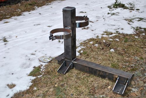
Yup, seeing a pearl band of mach diamonds from the engine would be a great reward.   I spent a couple of hours more on the test stand this morning so now the propellant tanks and the water tank are in place, the engine needs a steel plate mount welded to the stand that it can be bolted to and the ball valves and water pump needs to be fitted. Hopefully that will be fixed in a week or so.  The "custom paint job" on the 10L water tank is a couple of years old but still as fancy as when it was made during a punch drunk evening a week or so before Speed Weekend. ;D Cheers! /Anders |
|
|
|
Post by britishrocket on Apr 8, 2012 11:27:38 GMT -5
Hello Anders,
Really nice work on the test bed. What sort of water pump will you be using? I see you still have snow in Sweden. Ours has gone now, fortunately!
Thanks,
Carl.
|
|
|
|
Post by Johansson on Apr 8, 2012 11:38:06 GMT -5
I will use a 12V bronze gear pump capable of 15L/min, one of the scavange pumps from my gas turbine rig in fact.
I wish the snow here will go away soon so I can take my motorcycle for a trip, after 6 months of winter it will be great to ride again.
Cheers!
|
|
|
|
Post by Johansson on Apr 11, 2012 16:24:44 GMT -5
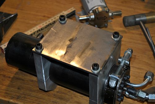
Today I got a handful of 1/4" hydraulic ball valves that I bought on Ebay and made a starting valve block out of two of them.  A lenght of rope will be used for starting the engine, I don´t think anyone I know is brave/stupid enough to manually open the valves... ;D  Cheers! /Anders |
|
|
|
Post by Johansson on Apr 12, 2012 10:27:09 GMT -5
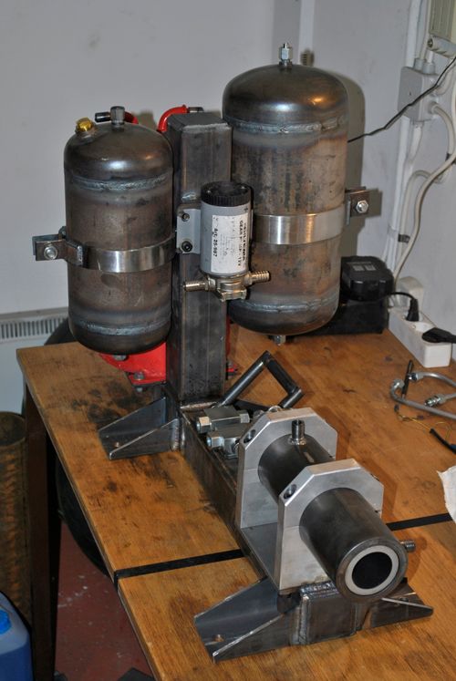
I quit work a couple of hours earlier today to get some workshop time while the rest of the family was away, so now all the major work on the test stand is done.   The water pump mount was made and welded to the test stand.  I drilled and threaded the holes for the throttle valve.  This is what the stand looks like now, next up is to do the plumbing and get some paint on it.  Cheers! |
|
mator
Junior Member
 
Joined: January 2012
Posts: 76
|
Post by mator on Apr 12, 2012 13:08:04 GMT -5
It looks magnificent!!!!
But as I understand you use two valves with same flow area for control lines of (oxidizer and fuel) with different mass flow rate. I know that this flows are quite close and if you don't want to change thrust in wide range this design solution will be good. I think about that when I think about my future developments.
What can you say about this problem?
|
|
mator
Junior Member
 
Joined: January 2012
Posts: 76
|
Post by mator on Apr 12, 2012 13:43:27 GMT -5
Do anybody knows, what is a day today?
|
|
|
|
Post by Johansson on Apr 12, 2012 14:07:44 GMT -5
It looks magnificent!!!! But as I understand you use two valves with same flow area for control lines of (oxidizer and fuel) with different mass flow rate. I know that this flows are quite close and if you don't want to change thrust in wide range this design solution will be good. I think about that when I think about my future developments. What can you say about this problem? Since I use 1/4" hydraulic tubing for all plumbing I have to use 1/4" valves as well to avoid pressure drop in the lines, I cannot see any problem with that since both the NOX and methanol injectors have a much smaller flow area than a 1/4" hole. |
|
|
|
Post by britishrocket on Apr 12, 2012 16:41:12 GMT -5
Hello Anders,
Great work. Yes you are right, the flow rate is ultimately dependent on the size of the hole in the injector. As long as everything else in your feed system is bigger than that you are fine.
Carl.
|
|
|
|
Post by Johansson on Apr 13, 2012 0:20:10 GMT -5
I will have to make the methanol feed line shorter than the NOX line since the fuel injector has only 50% of the NOX injector flow, it therefore takes twice as long for the fuel to push the air out of the feed line (after the ball valve) and reach the injector.
Preferably the fuel injection would start slightly before the NOX is injected so the spark wire gets soaked in methanol, I imagine that ignition will be easier that way.
|
|
|
|
Post by britishrocket on Apr 13, 2012 4:43:12 GMT -5
Hello Anders,
Hi, yes a fuel lead is undoubtedly desirable. It would help to prevent a hard start and any detonation by starting off with a richer mixture. Ideally you would want to start with a reduced propellant flow rate, as your propellant flows would have been calculated against the chamber pressure. At start up chamber pressure = atmospheric pressure. It is not so easy to do this with the set up you have, apart from opening the valves only fractionally to begin with.
I think though that if you start with a decent fuel lead you should be ok. The chamber pressure is going to ramp up pretty quickly in any case and your chamber should be able to withstand it.
Will be great to see it running and to see what chamber pressure you get and temperatures etc. Have you seen the stick on temperature indicators you can get? They are self adhesive strips that turn different colours depending on temperature. Might be worth having a few strategically positioned to try to get an idea of heat transfer.
Good luck,
Carl.
|
|