mator
Junior Member
 
Joined: January 2012
Posts: 76
|
Post by mator on Apr 13, 2012 13:23:28 GMT -5
Hello Anders, Great work. Yes you are right, the flow rate is ultimately dependent on the size of the hole in the injector. As long as everything else in your feed system is bigger than that you are fine. Carl. Yes. Here you Carl and Anders are correct. But I mean another thing. That relation angle of rotation of valve of liquid flow is not linear. Another words: (angle of rotation valve)/ (liquid flow)<>constant. It will be about linear if diameter of flow area of ball valve=area of injector. So as relation is not linear and flows and injector diameters are different, so you can get different components ratio (α) in chamber. |
|
|
|
Post by Johansson on Apr 13, 2012 13:56:41 GMT -5
I´ve thought about reducing the flow rate somehow during starting but the only practical alternative is to slowly open the valves until the engine lights and then open them fully.
A thermal strip on the thrust chamber wall would be very informative, but I doubt that it will survive being submerged in water. If it does I don´t think it will be very accurate when cold water is flowing past the upper side of it.
If I have a temp gauge in the water tank I might be able to calculate the heat transfer when I know the burn time of the engine.
Thanks a lot, a test run is still a couple of months away since we have to build a test rig with load cell and cast a concrete block in the back of my garden where it will be fitted.
Cheers!
/Anders
|
|
|
|
Post by Johansson on Apr 13, 2012 14:13:24 GMT -5
Yes. Here you Carl and Anders are correct. But I mean another thing. That relation angle of rotation of valve of liquid flow is not linear. Another words: (angle of rotation valve)/ (liquid flow)<>constant. It will be about linear if diameter of flow area of ball valve=area of injector. So as relation is not linear and flows and injector diameters are different, so you can get different components ratio (α) in chamber. Ok, then I understand what you mean. It doesen´t really apply here since the valves will be fully open all the time, I might have called them throttle valves earlier but what I meant was operating valves or whatever they should be called. |
|
|
|
Post by britishrocket on Apr 15, 2012 12:10:54 GMT -5
Hello Anders,
I have always intended to use a starting flow rate that would be provided by flow restrictors in the feed lines to reduce the flow based on there being the maximum pressure drop in the chamber before combustion starts. Then once the fire is lit and the pressure builds up, switch over to full flow. That was my original idea but I will be watching your progress very closely to see how your engine starts.
Have you seen the work of Robert Watzlavick? He is using LOX and Kerosine, and up until recently was using a similar ignition system to yours. His engine had a hard start recently and was damaged. I think that using Kerosine is causing him a lot of problems. The Kerosine tends to "crack" in contact with the hot chamber walls when used as a regen coolant, which is what he is doing.
Have you got your second edition of Sutton yet? If you have, P228 gives a method of calculating the chamber wall temperature and the mean coolant temperature rise. In order to do this you would have to make an estimate of the average heat flux. As I have mentioned elsewhere, for a small chamber this should be of the order of 3-4 BTU/in^2/sec.
It would be interesting to know what the cross sectional area of your chamber is so that I could do some check calculations myself. The reason I am so interested is that making good observations of your engine will help me to improve mine. It will also help to check the validity of the calculation methods I have been using.
I agree with you and think that a good measurement to take, if you are able to, will be the temperature of the coolant water as it leaves the cooling jacket. This will enable a fairly good estimate to be made of the gas side temperature, given that the thermal conductivity of the wall material is known, and that the assumption of the average heat flux is close to the actual value.
Best Wishes,
Carl.
|
|
|
|
Post by Johansson on Apr 18, 2012 23:29:27 GMT -5
Hi! Never heard of a Robert Watzlavick, do you know where to find info about his work? The book hasn´t arrived yet but should be here soon since it was dispatched the 12th this month. I will take some measurements of the chamber today and get back to you. That is the downside of running a Macbook, no AutoCad...  I got some propellant lines made a couple of days ago, been down with the feber since then but hopefully I will feel well enough to get some more work done in a couple of days. 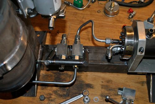 As you hopefully can see the NOX line is more than twice as long as the methanol line, so in theory the fuel should arrive just before the NOX. We´ll just have to wait and see how well reality matches theory in this case.  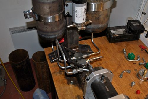 Cheers! |
|
mator
Junior Member
 
Joined: January 2012
Posts: 76
|
Post by mator on Apr 19, 2012 2:52:45 GMT -5
Ok, then I understand what you mean. It doesen´t really apply here since the valves will be fully open all the time, I might have called them throttle valves earlier but what I meant was operating valves or whatever they should be called. I think that it is that answer that I wanted to hear. Ok. Where did you get tubes for components lines? |
|
|
|
Post by Johansson on Apr 19, 2012 5:31:33 GMT -5
They are regular hydraulic lines and couplings, every seal in contact with liquid NOX will be changed to teflon later.
|
|
|
|
Post by Johansson on Apr 19, 2012 14:17:49 GMT -5
More work done, today I started making the tubes for tank pressurisation. 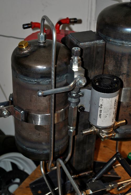 My old trusty tube bender, only intended for bending copper tubes so it has obtained an impressive flex in every joint over the years... ;D  I use one way valves on both tank pressurising lines to insure that there cannot be any mixing of NOX and methanol in the lines in case a pressure difference between the two tanks occurs, that would be very dangerous indeed.  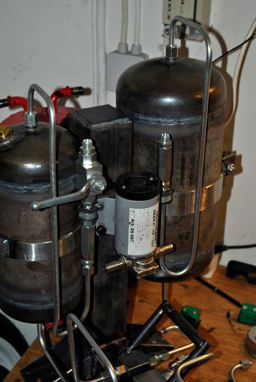 Cheers! |
|
|
|
Post by britishrocket on Apr 20, 2012 6:17:37 GMT -5
Hi Anders, Great work, nice to see so much progress. Wish I could say the same about my workshop! You can find Robert Watzlavicks work here:- www.watzlavick.com/robert/rocketHe is in the US. The last time I spoke to him he was quite uncommunicative; he seems to be very concerned that talking about his project would infringe ITAR regulatiuons. It would be superb if you could give me the figure for the heat transfer of your engine. When I said cross sectional area I was quite misleading. What I meant was the area of the cylindrical portion that is in contact with the cooling water. Best Wishes, Carl. |
|
|
|
Post by turbochris on Apr 20, 2012 7:32:04 GMT -5
you can modify the "fuel schedule" of a ball valve by grinding the opening in the ball. Just make some slots on the trailing edge and when it closes it's more linear, not an abrupt cutoff. If you're looking for high flows maybe the slots will cause too much turbulence. Maybe modify the ball hole and seats to more of a teardrop cross section.
Considering the throttle handle for this thing will be bent in the "doing work" direction like the handles on your tube bender, I guess this comment was pointless.
I've seen some people put model trains and villages in their gardens, Anders will have NASA
Chris
|
|
mator
Junior Member
 
Joined: January 2012
Posts: 76
|
Post by mator on Apr 20, 2012 12:58:08 GMT -5
He don't deeds in some special "fuel schedule" . He said that his engine will have only two positions: on and off.
|
|
mator
Junior Member
 
Joined: January 2012
Posts: 76
|
Post by mator on Apr 20, 2012 13:06:12 GMT -5
I use one way valves on both tank pressurising lines to insure that there cannot be any mixing of NOX and methanol in the lines in case a pressure difference between the two tanks occurs, that would be very dangerous indeed.  One way valves that you use are same to valwes that are used in standart gas cutting metals equipment? |
|
|
|
Post by Johansson on Apr 20, 2012 14:51:48 GMT -5
Hi Anders, Great work, nice to see so much progress. Wish I could say the same about my workshop! You can find Robert Watzlavicks work here:- www.watzlavick.com/robert/rocketHe is in the US. The last time I spoke to him he was quite uncommunicative; he seems to be very concerned that talking about his project would infringe ITAR regulatiuons. It would be superb if you could give me the figure for the heat transfer of your engine. When I said cross sectional area I was quite misleading. What I meant was the area of the cylindrical portion that is in contact with the cooling water. Best Wishes, Carl. Looking at the spray pattern on his 250lbs LOX/kerosine injector really makes me appreciate my choice of NOX as oxidizer, the multiple injector holes forces him to use a very low injection pressure (he has that choice since LOX hasn´t anywhere near as high vapour pressure as NOX has) which makes the spray pattern very narrow.  My crude triplet O-F-O impingement injector gives a much wider spray pattern even at only 10 bar pressure drop, so it will be very interesting to see how it performs. I strongly dislike overworking things without knowing if it is needed or not.  |
|
|
|
Post by Johansson on Apr 21, 2012 9:26:29 GMT -5
Sorry for the delay Carl, here are the thrust chamber measurements. The chamber outer diameter is 60mm. 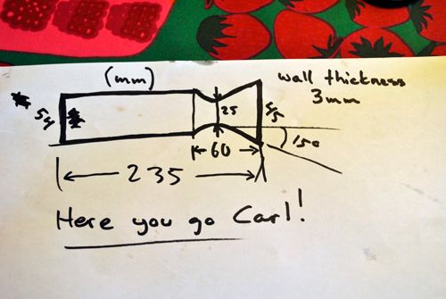 Cheers! |
|
|
|
Post by britishrocket on Apr 22, 2012 8:58:59 GMT -5
Hi Anders,
Thanks for the dimensions, I will do some heat transfer calculations and get back to you on it.
It looks like that picture of Watzlavicks' injector shows it flowing water at relatively low pressure through both the fuel and oxidiser orifices. I think though that it probably doesn't have that wide a spray angle even with the LOX and fuel flowing at design pressure. The Americans seem to be very enamoured of the impinging hole injector. In my opinion it makes for more complex manufacture, trying to drill the small angled holes. I also rejected this type of injector on the grounds that mixing and atomisation will be poor in the shorter length of chamber usually found in small rocket engines. I think that this is borne out by videos of engines with this type of injector running. Often evidence of incomplete combustion can be seen in the exhaust.
Still working on the post for my own site showing the results of the shear coaxial injector. They will show the attempts I made to improve it and why I started moving towards a swirl coaxial model.
Thanks to you Anders and Mator and everyone else on this forum who are contributing to the collective pool of knowledge.
Best Wishes,
Carl.
|
|