|
|
Post by racket on Jan 11, 2011 1:47:30 GMT -5
Hi Anders
Perhaps countersunk socket headed screws for the deflector with plenty of Loctite on the "long" threads in the alloy , if theres more thread in the alloy than distance between deflector and flametube the screws can't completely unscrew , they'll hit the FT first , I've only got my deflector screws Loctited and a spring washer under the screw head, I would have prefered lockwire bit it wasn't convenient .
With countersunk screws , if your turn the head down to a sharp outer edge/corner then cut a little slot on the outer edge/rim , you can centre punch some of your deflector metal into the slot to give a positive lock , I've used this method on occasion and it sorta works , looks a bit untidy , but heh , no one will see it :-)
I'd still be inclined to have a ring of screws on the forward end of your outer can , theres a lot of air pressure force on that rear wall and a redhot NGV weld might become a bit soft
O'ring will need to be silicone , I've found that the normal black ones are too hard over such a large diameter that its difficult to get the can to slide over it unless tolerances are very close , the softer silicone rings have a bit more "give" which allows the O'ring to better "adjust/squash" to the diametric clearance between can and alloy housing.
Cheers
John
|
|
|
|
Post by ernie wrenn on Jan 11, 2011 11:39:28 GMT -5
|
|
|
|
Post by Johansson on Jan 11, 2011 14:33:50 GMT -5
I´ll see what I can come up with regarding the deflector bolts.  I didn´t think about how the air pressure will affect the lid, perhaps it would be best to fit a couple of screws there just in case. Good pointer about the silicone O-ring, I´ll try to find one in the right diameter. |
|
|
|
Post by Johansson on Jan 11, 2011 15:10:48 GMT -5
I bought a 4" V-band flange today which will be used to fit the jetpipe to the turbine shroud, I have to massage it a bit in the lathe to get the inner diameter right though.
Olov (my friend with the jet kick) has borrowed me a larger brushless motor than the one I have, hopefully it will be powerful enough to start the engine with. 20.000rpm at 22V and max 80A.
|
|
|
|
Post by Johansson on Jan 15, 2011 9:13:54 GMT -5
I spent four hours in the workshop today and got lots of work done.  First of all I added a guide vane inside each air deflector between the diffusor exit holes. 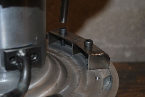 Then I milled away some material from the diffusor lid where the engine cover will be mounted. 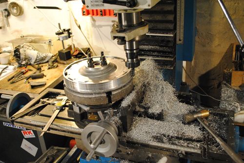 Milling an O-ring slot. 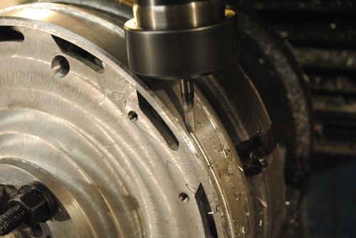 And the result, later I will add bolts around the edge to hold the engine cover, btu that will have to wait until I have made the cover. The O-ring will be made in silicone. 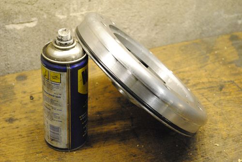 I also made some cosmetic touches to the compressor shroud. 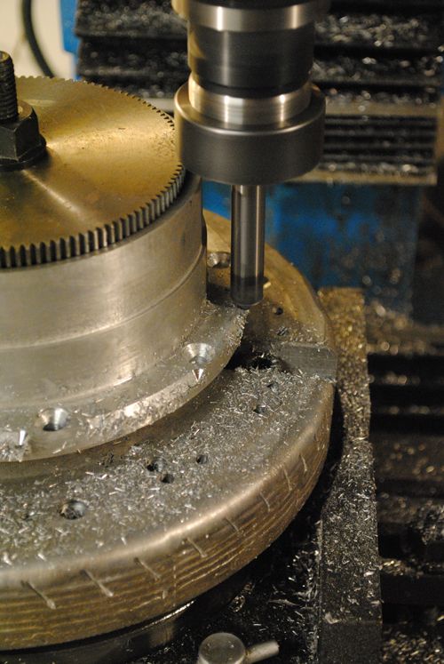 Looks a bit better than just a straight edge I think. 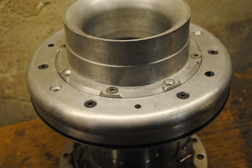 After that I fitted the V-band flange to the turbine exducer shroud, the turbine outlet diameter is a couple of mm´s larger than the 4" flange but since the turbine wheel hub is "dead" area the 4" flange and turbine wheel has roughly the same flow area. 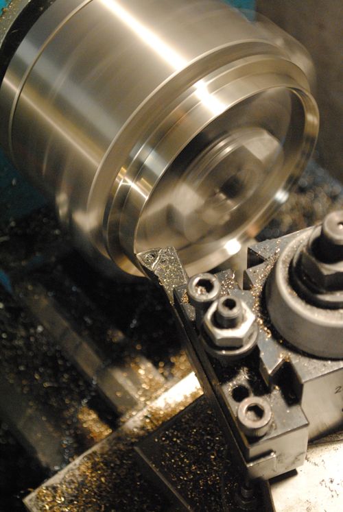 Welding the parts together, quite exciting since I don´t want anything to warp from the heat... 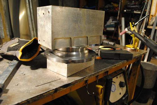 Tacked together, everything looks straight so far. 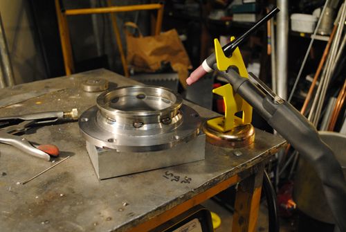 And finished, no noticeable warping at all. 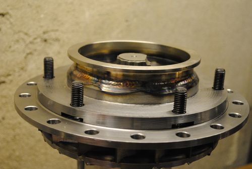 Cheers! |
|
turborico
Member
 
Joined: December 2010
Posts: 24
|
Post by turborico on Jan 15, 2011 13:21:00 GMT -5
Amazing work!
|
|
|
|
Post by Johansson on Jan 18, 2011 15:31:58 GMT -5
Thanks a lot! Hopefully I won´t have to rebuild much after the first startup tests.  I made 18 vapour tubes from SS2348 (316) and fitted them to the turbine housing, I can´t weld them before I have sent the housing away for cheramic coating. 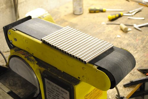 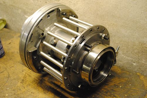 As you can see there is very little room for a fuel manifold behind the vapour tube entrance, there is aprox. 15mm axial clearance to the engine cover so I will have to make an external fuel manifold fitted to the engine cover instead. This is not all bad since I can spot fuel leaks immediately and in case of a bursted fuel line the engine will stop instead of rev up uncontrollable, the downside is slightly more complex plumbing. Cheers! |
|
|
|
Post by racket on Jan 18, 2011 17:26:09 GMT -5
Hi Anders
LOL.................15mm , what luxury :-) ................plenty of room for a fuel manifold .
One of the reasons I used a concave endwall in my 10/98 engine as well as FM-1 was so there was a "corner" where fuel manifolds could be easily tucked.
In my 9/94 engine with its nice rounded corner and flat rear wall, things were a lot tighter, but there was just enough room for a 3/16'" fuel delivery line to wrap around the edge of the FT rear wall and join a 1/4" manifold that the injectors were silver soldered into , you only need a couple of millimeters axial clearance between evaporator end and the fuel manifold , so if we total up the distances , as long as you've got 10mm between NGV and outer can , it should be possible to fit a fuel manifold .
Its going to be very difficult to align injector and evaporator if its coming thru from the rear , theres also the sealing of 18 separate fittings , it'll be an enormous amount of work compared to an internal manifold , you need to be able to inject against the evaporator wall as well .
Lots to consider :-(
Cheers
John
|
|
|
|
Post by Johansson on Jan 19, 2011 0:52:17 GMT -5
So you think it is possible to fit an internal manifold? Well then I´ll give it a try, in case it won´t work I´ll always have the option of making an external one later.
|
|
|
|
Post by racket on Jan 19, 2011 16:43:01 GMT -5
|
|
|
|
Post by Johansson on Jan 20, 2011 1:27:56 GMT -5
Ok, so I can have the fuel manifold so close to the vapour inlets without messing with the air flow? Then it won´t be a problem.  |
|
|
|
Post by racket on Jan 20, 2011 2:01:44 GMT -5
Hi Anders
Yeh , I've had a look at the evaps/fuel manifold on a baby Jet Joe Junior engine and the manifold is virtually sitting on the evap ends .
With the evap end being slightly bellmouthed ,so it can't fall into the FT if something goes wrong with its fixing method , the airflow into it is pretty good , and as with any flow into a hole we only need a quarter of the hole diameter as an axial clearance to produce the hole area , and as the manifold is nicely rounded and only ~6mm dia theres plenty of room for airflow , I've had no problems with evaporator ends burning off from overheating so theres plenty of air going thru them .
You'll be right mate :-)
Cheers
John
|
|
|
|
Post by Johansson on Jan 21, 2011 5:14:48 GMT -5
I´ll counter sink the holes in the NGV plate just to make sure that enough air gets onto the tubes. Now I have to go digging, I have a lenght of 30cm diameter 316 stainless pipe under 60cm of snow somewhere behind my fathers shed. I think I can use the 90 degree bend for something...  |
|
|
|
Post by Johansson on Jan 21, 2011 11:13:33 GMT -5
My memory failed me again, the pipe was 20cm in diameter and not 30cm. It might still work if I make a transition between the ~30cm power turbine housing and the exhaust bend. I would have prefered a slightly tighter bend but it should still be usable, the two bends will be cut loose and welded together and can most likely be massaged into something that works.  |
|
|
|
Post by Johansson on Jan 25, 2011 1:10:17 GMT -5
I spent last night in the workshop trying to figure out a good way to make the starter, I came up with a working (hopefully...) idea and got halfway to a finished starter before I had to call it a night. 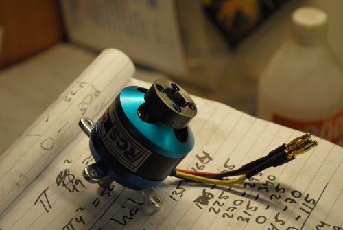 Lets just hope that the starter is strong enough so I won´t have to do this all over again with a larger motor.  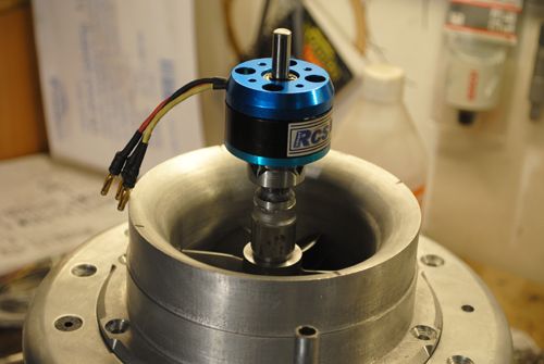 With the starter coupling made I milled four holes in the compressor cover where stainless rods were to be inserted and screwed in place, the rods are sunk almost 30mm into the aluminum to add stability to them and at the bottom there is a threaded M5 hole that the rods was screwed into. They won´come off, I promise.  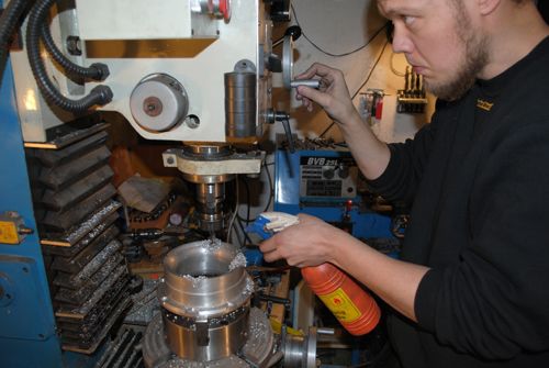 Here is as far as I got, left to do is to make a lid that bolts to the top of the rods and make the motor mount with 10mm holes at each corner where the rods will be. 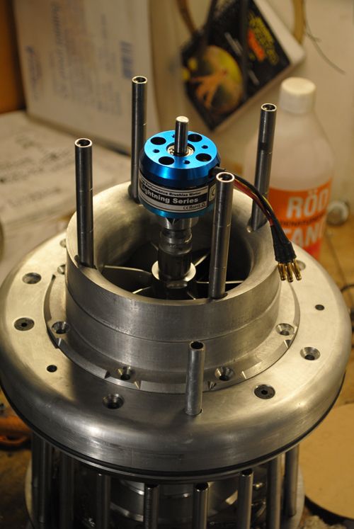 Four springs will sit between the motor mount and the compressor cover so I have to manually press the motor against the compressor nut, as soon as I release it (by solenoid or some sort of manual catch) the motor will disengage the compressor nut. Hopefully. ;D |
|