|
|
Post by Johansson on Oct 8, 2013 4:40:27 GMT -5
Hi Anders OK, we should be able to rule out the oil forcing things aside. You'll need some sort of locating devices , on the 10/98 and all my engines I use a turned rebate in the rear of the diffuser wall that the shaft tunnel fits into to provide concentricity .............LOL, the SKULD has a 115mm dia by 4 mm deep rebate for a 115mm OD shaft tunnel to fit into. The 5mm spacer shouldn't be a problem if ground flat, on both the FM-1 and 9/94 engines I used a home made piston ring holder behind the comp wheel that displaced the comp as far forward as I could so that the flametube was as long as possible , when I made the 10/98 the comp wheel went further onto the shaft which meant a shorter flametube , but it still worked OK thankfully . There is a slight increase in diameter of the comp shaft quill just before the comp is fully home on the quill , that increase in diameter is to positively lock the comp radially, by having the comp further forward on the quill there is a chance that the wheel won't be accurately fixed , but I don't think it could have caused your problem at the low power setting you were using ...............more likely lack of concentricity between shaft tunnel and diffuser wall. LOL...... it was a bugger of a job getting the 10/98 engine made using the standard bits without a comp spacer , there wasn't much available space to fit the thrust bearing and the piston ring shroud , thats why I fitted the stainless piston ring shroud sleeve into the alloy diffuser wall , even on a turbocharger those parts are kinda "fragile" as the bits are rather thin and is the reason the back wall of a turbo comp housing often needs replacing after minor bearing problems . Yep, I'll look forward to helping get things sorted :-) Cheers John Hi John, I´ve taken the engine apart and taken pics of all the internals (update with pics coming tonight) and luckily the journal bearings and their housings look ok. The turbine shaft seems straight as far as I can measure, I got a 2/100mm throw over the entire shaft but that is probably caused by the lathe. Hi Anders I recently found a bit more updated technical info on the TV94 bearings at TurboMaster whilst researching for info to help with the Skuld build , heres a Link to the page www.turbomaster.info/eng/turbos/technical_data/garrett_TV94/Also the bearings should be between 30.4597 and 30.4724 mm OD , with ID of 21.5849 to 21.5976 mm by 13.8684 mm wide. Cheers John Thanks for that, I measured the journal bearing/housing clearance last night and got a 0.21mm diametrical difference on both the front and the rear bearing so it is the same as when it was new. With radial clearance do they mean the clearance on one side or the total clearance on both sides (difference in diameters)? As I´ve been taught a radial clearance is measured on the radius, i.e. from the shaft centre and out to one side. According to your link the clearance should be between 0.08mm and 0.18mm, so it can be either spot on or a tad to sloppy depending on the terminology. I´ll measure the bearings when the kids are asleep. =) Cheers! /Anders |
|
|
|
Post by Johansson on Oct 8, 2013 4:49:40 GMT -5
put a little accumulator on there, just enough to keep it lubed as it spools down. That would be a pretty large accumulator to keep the oil flow going for the ~10 seconds it takes for the rotor to stop... Keeping a 12V oil pump running is normally not a problem, with a quality switch there should be no more problems so I don´t think I will overwork this. I could add all kinds of safety functions but in the end I am just adding more and more stuff that can cause problems later on. Wolfdragons suggestion falls into this category as well, a very good idea but I don´t think it is necessary. |
|
|
|
Post by Johansson on Oct 8, 2013 4:55:14 GMT -5
Hi Anders, When I was having a look at your weight summery for the bike, it twigged a question in my mind based on the weights for B1 to date and I was wondering how in the world you got the weight down so low? With the heavy battery and cast iron gearbox, you got an amazing 163.3kg. I initially used the same method to establish weight for B1 and based on what the figures said, assumed my scales were badly out and basically weighed each component as best I could using another much smaller scale that I believed was accurate and added the sum of all parts to arrive at a weight...it appears I was patently wrong (as was the smaller scales). I just borrowed the neighbors scale from two of my neighbors as the first one appeared to be wrong like mine: they weren't. B1 with batteries and fluids (no fuel) turns out to be just on 170kg. and reasonable effort has gone into getting most of the components down in weight for the project. B1 is all alloy, 'including' the gearbox and like yours, has the barest minimum of operating components. I am going to be very hard pressed just to drag the dry weight down to 165kg. Very well done on the build..now I am hanging out badly to see her flying down the track  Regards, Andrew Hi Andrew, I think the frame weight is what makes my bike so light, a CrMo tubular frame don´t weigh many kilos while a cast aluminum motorcycle frame is pretty heavy. You had oil in your bike as well. Also bear in mind that I haven´t used a reference scale or anything, just my IKEA bathroom scale. It might differ a kg or so for all I know, even though it seems accurate enough when I use it myself. I think the gearbox and battery weight is a good thing for me to get enough traction at high speed on slippery surfaces, with a feather light rear I could end up with traction problems and have to use lead weights to correct it. Cheers! /Anders |
|
|
|
Post by Johansson on Oct 8, 2013 14:31:09 GMT -5
Yesterday I disassembled the engine completely to measure everything and take some pics of the parts, first up is the piston ring sleeve which has severe rubbing marks at 4 o´clock seen from the intake and wear marks from the seized rings all around. 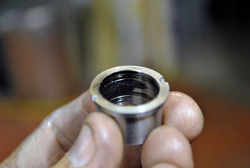 The next picture is the thrust washer which has some wear marks mainly on one side 2 o´clock seen from the intake. If I remember correctly there were some marks there even before this run. 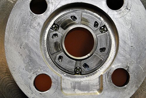 Then it is the thrust bearing, no major damage but a small heat pattern in one spot as you can see. 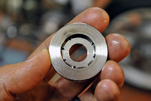 The comp wheel spacer is a mess, both rings stuck in their grooves. (I´ve posted this pic before) 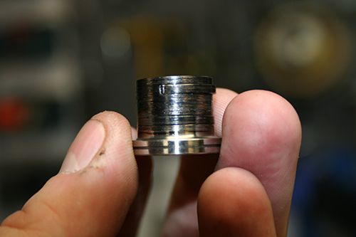 The spacer ring has a heat pattern that matches the comp wheel spacer, not surprisingly since it sits just behind it. No damage to the end surfaces so it can be reused, good thing since it is precision grinded by a friend. 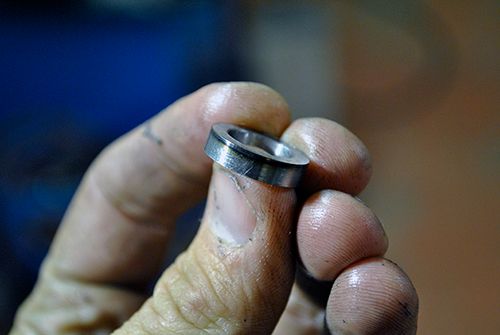 Finally the rear thrust washer, no heat signs but the thrust bearing has grinded itself into the washer a few 0.01´s of a mm. Might prove that the axial clearance has seized up somehow. 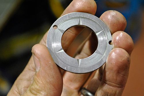 I measured the shaft in the lathe and it runs true within 0.02mm which might very well be caused by the lathe. 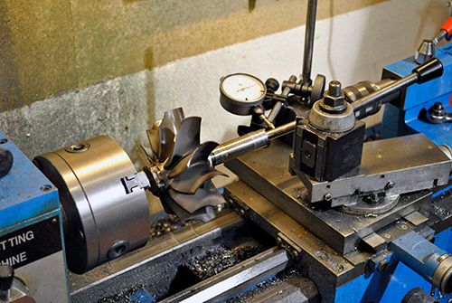 One thing I found that might cause trouble is the journal bearing bore diameter, I remember now that when I asked John about the clearance I misunderstood him and made the clearance twice the recommended value (the radial/diametrical misunderstanding...). The max bore is according to Garrett 30,607mm and I measure both bores to 30,670mm.  Any thoughts on this? Cheers! /Anders |
|
ripp
Veteran Member
   I'm sorry, I don't speak english, so I torment you (and myself) with a translation program,Sorry
Joined: January 2013
Posts: 237
|
Post by ripp on Oct 8, 2013 15:49:07 GMT -5
Hi Anders,
the spacer ring is 0,5mm smaler then the hole(borg warner turbocharger s400),is it the same for you?
Cheers
Ralph
translate.google.at
|
|
ripp
Veteran Member
   I'm sorry, I don't speak english, so I torment you (and myself) with a translation program,Sorry
Joined: January 2013
Posts: 237
|
Post by ripp on Oct 8, 2013 16:03:35 GMT -5
and the oil supply is really through the small holes of the thrust washer so the oil does not pass outside?
Cheers
Ralph
translate.google.at
|
|
ozbooster
Member
 
Joined: October 2013
Posts: 28 
|
Post by ozbooster on Oct 8, 2013 17:04:54 GMT -5
Anders you know me as Maj on Landracing
Can you assemble the shaft,bearings compressor etc and check in the lathe like you have the shaft pictured, just to be sure your runout does not change when assembled , also let you accurately check the cold end float
|
|
gidge348
Senior Member
  
Joined: September 2010
Posts: 426 
|
Post by gidge348 on Oct 8, 2013 19:28:05 GMT -5
With radial clearance do they mean the clearance on one side or the total clearance on both sides (difference in diameters)? As I´ve been taught a radial clearance is measured on the radius, i.e. from the shaft centre and out to one side. According to your link the clearance should be between 0.08mm and 0.18mm, so it can be either spot on or a tad to sloppy depending on the terminology. Cheers! /Anders
According to :http://www.maintenanceresources.com/referencelibrary/bearings/gobt.htm
Radial Clearance
The radial internal clearance of a single row radial contact ball bearing is the average outer ring race diameter, minus the average inner ring race diameter, minus twice the ball diameter.
So I guess they are talking about the difference in diameters, not the difference in radius. So the dimensions could be a touch sloppy, but I cant see how too much clearance would cause the problem.
Ian... |
|
gidge348
Senior Member
  
Joined: September 2010
Posts: 426 
|
Post by gidge348 on Oct 8, 2013 19:30:45 GMT -5
I am not totally familiar with how this engine goes together but from an outsiders failure analysis.... It is looking to me as though it all started with a lack of oil distribution in the area of the piston ring sleeve. The wear at 4 o'clock on the sleeve may be that it just decided to grab at any random point on the sleeve and then drag material around, if it was left to run longer I am sure you would have seen marks around the full circumference. I assume?  the piston ring sleeve is in the same area as the front thrust bearing so as oil poured out of the damaged sleeve and temp went up this lead to oil starvation on the front thrust bearing. As this got hotter and expanded tightened the spacer and the rear thrust bearing leaving the marks. I am not sure that the bore of 30.670mm instead of 30.607mm would be a huge problem as long as the oil pressure was kept up and the shaft was balanced. I can't see any damage that screams vibration as the problem? One thing I am interested in was what type of oil you are using? Cheers Ian... |
|
|
|
Post by racket on Oct 8, 2013 19:43:44 GMT -5
Hi Anders
The sleeve certainly appears to indicate misalignment between diffuser housing and shaft tunnel , a couple of locating dowels should fit that , theres not much clearance between the holder and shroud as those rings are rather thin and if we want to keep ring gap at reasonable levels we have to have good alignment .
Thrust washer wear ......if the thrust washer pocket and the diffuser to shaft tunnel face were machined at the same time then the thrust surfaces of the pads should be all the same and wear should be over all of them ....BUT .....when I measured the heights of the thrust pads to diffuser rear face on the 10/98 after initial installation I found they were of slightly different distances , initially I thought I'd stuffed up somewhere with the machining , but after lotsa measuring I found that the thrust washer pad heights weren't equal , I felt it was a result of its manufacturing process , and it would "run in " after a bit of use .
The "isolated" wear spot on the rotating component of the thrust washer is more of a concern as it indicates either its not running true or that the shaft was wobbling from an out of balance , and/or exacerbated by the lube failure................you will need to fit everything back onto the shaft quill and torque up the nut to specs and check for true running of the components .
Piston ring holder is nice and coloured all around which sorta indicates it was running relatively true against the ring shroud , or jammed so hard against it that it didn't have a chance to move away even if slightly out of true .
Non rotating rear thrust surface .........if you place a straight edge across it can you see if the wear is "tapered" away from the centre , if most of the wear is at the outer edge its probably been caused by the rotor wobble/gyrations , its only a buffer bearing to fix end float so shouldn't be showing any wear as thrust is always forward , but the problems further forward have most likely caused a rearwards force and jammed the rotating component hard against it .
Shaft tunnel bore .............your 30.670mm should be OK , the Garrett 30.6070 allows for some wear of the rotating bushes after a few thousand hours of work,(the cast iron centre housing doesn't generally wear much) before problems appear with attaining their design rpm, and as you are using new bushings and will probably never have worn ones in the engine it shouldn't be a problem .
The bearings are 30.4597 mm minimum diameter, so you'll have a maximum diametric clearance of 0.2103mm , radially 0.10515mm well within the 0.0800- 0.1800mm range.
Now the TurboMaster data is a little vague as to whether or not the "radial clearanc" is just the bush OD to bore clearance or if the shaft to bush ID clearance is also added on , the shaft to ID clearances are much smaller than the OD ones , its a balancing act to get the driving torque to friction ratio just right to achieve the correct bush rpm, so even if the maximum shaft to bush ID radial clearance is added on , ~0.025mm , you're still nicely within the range .
Some new bearing bits , a balance , a couple of locating dowels , and she'll be ready for more action :-)
Cheers
John
|
|
|
|
Post by racket on Oct 8, 2013 19:58:28 GMT -5
|
|
|
|
Post by racket on Oct 8, 2013 20:36:09 GMT -5
Hi Anders
I just went and measured a bearing I have here and it came in at 1.1996" (~30.472mm ??), at the upper end of the range for ODs ,
The standard turbo shaft tunnel bore range is within 0.0005" ....half a thou , thats a pretty tight range , so not much room for that to influence the clearance range ................the bearings are also within a half thou diametrically , so a max of one thou diametrically between minimum and maximum mix of parts yet the "Radial??" bearing clearance is between 0.003 and 0.007" ,......they've gotta be allowing for worn parts.
Lube temperature will also play a big part in the rotor dynamics , I doubt you'll ever be running the same temps/viscosity as a big diesel thats been on full throttle for hours on end , cooler/thicker lube will "decrease??" your clearances ..............its complicated :-(
I strongly doubt your problems were related to bearing clearances at the low rpm you were running at the time .
Cheers
John
|
|
gidge348
Senior Member
  
Joined: September 2010
Posts: 426 
|
Post by gidge348 on Oct 8, 2013 20:53:09 GMT -5
John that makes total sense, if the front and rear bearing (and/or) mounts are not concentric (after torqueing) for what ever reason that would give the problems we see here.
Ian...
ps. I have had a quick look through the paper you linked and I can see there are a huge number of different loads and dynamics going on there.
|
|
|
|
Post by finiteparts on Oct 8, 2013 23:55:00 GMT -5
Sorry to hear about your minor snag...it may be small comfort that even the big companies with teams of engineers have growing pains too. I had a few ideas that I thought might be worth throwing out there. When a journal bearing "lifts", the rotational motion of the shaft sets up a hydrodynamic wedge and the stable equilibrium position of the shaft centerline can be offset to the location similar to the 4 o'clock position to your wear mark. (See Figure 1, www.intechopen.com/books/tribology-fundamentals-and-advancements/lubrication-and-lubricants). If you ran low on oil flow, the rotor may have begun to climb and caused the wear, or you could have entered a whirl/whip mode on the rotor (since its rotordynamic behavior is a function of bearing stiffness, which is a function of flow rate and viscosity (which itself is a function of temperature)). The literature on hydrodynamic journal bearings commonly refers to both reduced oil supply pressure and increased outer journal clearances as a means to reduce the threshold speed at which the rotor enters instability. It's hard to think that 0.002 inch increase in clearance would cause a problem, but maybe a small increase in the bearing OD clearance changed the RPM where the instability mode is entered on the outer journal...that is one of the challenges of floating journal bearings, the opportunity to get instabilities in both the outer oil film and the inner film, thus the complicated non-linear response of these systems. The other big challenge is that journals must pass through various sub-synchronous (less the one per revolution) vibrational modes before they reach the challenge of the synchronous vibes (one per revolution...like an out of balance)...but that being said, if you stay true to the original design, it really shouldn't behave differently? The first instablity mode usually entered by the rotor is a conical mode (shown in Figs. 5 and 14 in the paper John provided the link to), which would cause a large centerline deflection at the compressor end, thus maybe why your piston rings were so worn? I look forward to seeing your next steps and wish you good luck! Chris |
|
jdw
Member
 
Joined: January 2012
Posts: 41
|
Post by jdw on Oct 9, 2013 2:21:50 GMT -5
Sorry it has been a long time since I have posted but on such an event I must break my silence. I do lurk here EVERY day though  Anders amazing build and hope all works well and you kick Murphy in the teeth;) But my main reason to post is I think Racket and yourself should be elevated to "Turbine God" status;) I could explain more but the alcohol is free flowing this evening impairing my typing skills. Best of luck and hope to see the beast roar to life. On aside note have you named her yet?? If not I nominate BITCH for her name. JDW |
|


 the piston ring sleeve is in the same area as the front thrust bearing so as oil poured out of the damaged sleeve and temp went up this lead to oil starvation on the front thrust bearing. As this got hotter and expanded tightened the spacer and the rear thrust bearing leaving the marks.
 Anders amazing build and hope all works well and you kick Murphy in the teeth;) But my main reason to post is I think Racket and yourself should be elevated to "Turbine God" status;) I could explain more but the alcohol is free flowing this evening impairing my typing skills. Best of luck and hope to see the beast roar to life. On aside note have you named her yet?? If not I nominate BITCH for her name.