|
|
Post by Johansson on Apr 23, 2014 23:17:29 GMT -5
Now when the holidays are over I found time to start working on the gearbox, I fitted the gas producer to the frame to free up some space on the work bench and it looks like it has found a good home.  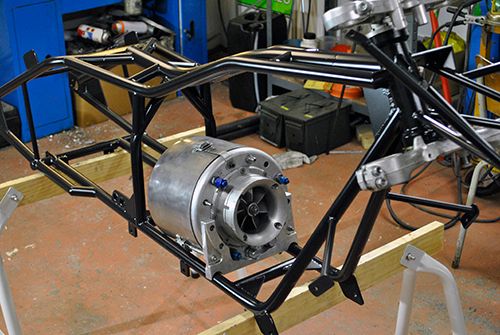 Taking the power turbine section apart to get to the gearbox. 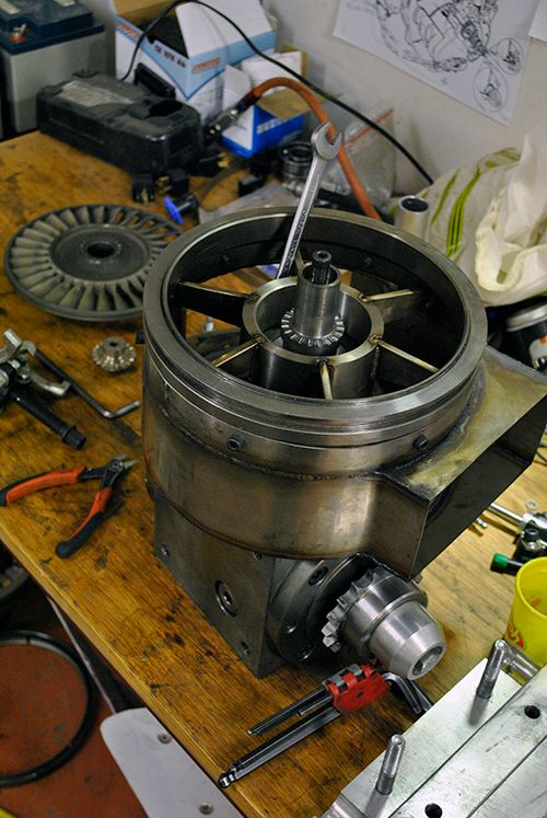 Here you can see the output shaft gear... 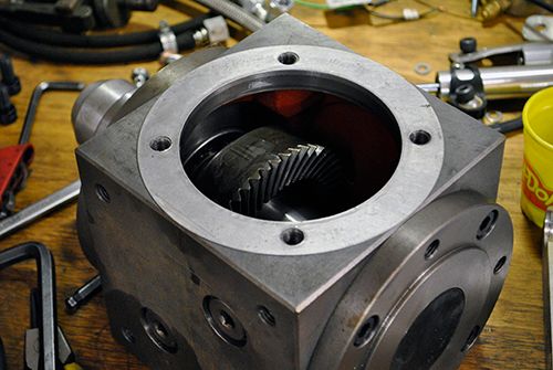 ...and here is the input shaft housing, now you have seen the two spots in the gearbox that is a bit tricky to lubricate properly. 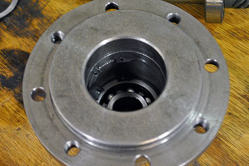 I spent over an hour staring at the parts trying to figure out a way to do this, I have had discussions with John and the way we decided then was to direct a jet of lube on each input bearing and one directly into the gear mesh but looking at it now that won´t be easy to do. I would either have to bleed oil from the main pump and connect the gearbox and oil tank somehow or fit yet another oil pump to the bike and run a closed loop inside the gearbox, but since I already have four pumps running from the battery I´d rather not do that. 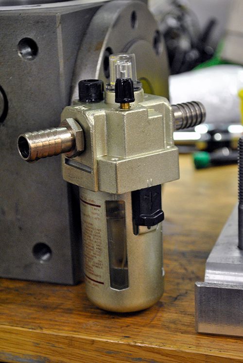 I came up with a bit of a special solution for now, I will run a wet sump that will keep the <5000rpm output shaft and bearings lubricated and route bleed air through an oil mist lubricator (used for lubricating pneumatic tools) and into the input shaft tunnel between the bearings. The hybrid bearings don´t need much oil and the bleed air will cool them and provide an air flow that will keep the exhaust gasses from entering the shaft tunnel. All I need to do is trim the oil flow and keep a close watch on the oil level in the oil mist lubricator so it won´t run dry but that will only be another point on the pre run check list. I´ll inspect the gear mesh and bearings after the first couple of runs to check for signs of oil starvation and wear, if it shows any signs of damage I will simply have to rethink. This is the easiest way of doing it and I like easy.  Cheers! /Anders |
|
gidge348
Senior Member
  
Joined: September 2010
Posts: 426 
|
Post by gidge348 on Apr 23, 2014 23:44:57 GMT -5
|
|
|
|
Post by Johansson on Apr 24, 2014 3:39:04 GMT -5
Hi Ian,
I can´t open the link on my work computer so I´ll check it tonight, I´ve talked this through with Olov and it feels like I am on the right track.
The latest idea is to make a solid aluminum block ejector with a needle valve for the oil, the 200C bleed air won´t be kind to a standard plastic mist oiler so I need something a bit sturdier. I will also do away with the separate tank and pull the misting oil directly from the gearbox sump, a thin enough oil should be able to suck the 15cm or so up to the top of the gearbox with 1-2.5bar of bleed air blowing through a 2-3mm tube.
I´ll make a test ejector and try it out to see how it performs.
Cheers!
/Anders
|
|
gidge348
Senior Member
  
Joined: September 2010
Posts: 426 
|
Post by gidge348 on Apr 24, 2014 21:15:16 GMT -5
Hi Anders, just wondering as well, how the 200C air will affect the oil viscosity? Do you think it may be worth looking at some type of heat exchanger? With my engine, bleed air is available at 83psia & 270C, John has recommended using water/methanol injection so I will be carrying about 30L of water/methanol. Temp is a good thing for water injection, been thinking about using a radiator oil cooler in the water tank to cool the air that goes to the diff oil if I use a mister?  Still more thinking to be done??? Be interested to see how yours works? Cheers Ian... |
|
|
|
Post by Johansson on Apr 25, 2014 10:53:58 GMT -5
Hi Ian,
I have planned to make some sort of heat exchanger, probably a couple of turns of copper tubing for the bleed air so it chills down a bit before reaching the oil/air ejector. I´ve been trying some designs out on my lunch hour at work and I think I am on to something, will post a summary once I have decided on how to design it.
Cheers!
/Anders
|
|
|
|
Post by Johansson on Apr 25, 2014 14:49:51 GMT -5
Yesterday the M12x1.0 die I ordered a couple of weeks ago arrived so I could finish lowering the fork legs. 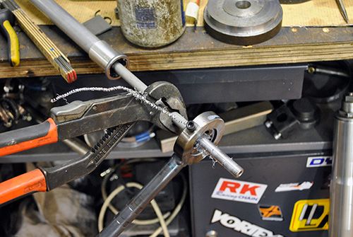 I shortened them 6cm which feels about right, this particular fork needs to have the inner damper tube cut and rethreaded when the Hayabusa forks and others only needs to have the spring spacers replaced. 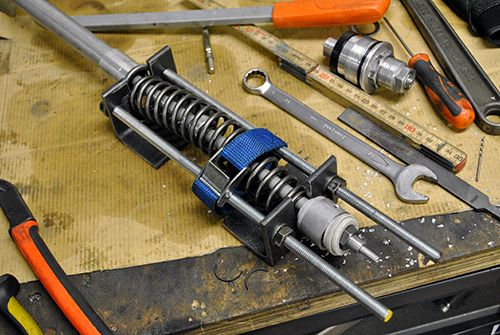 One leg done, one to go. 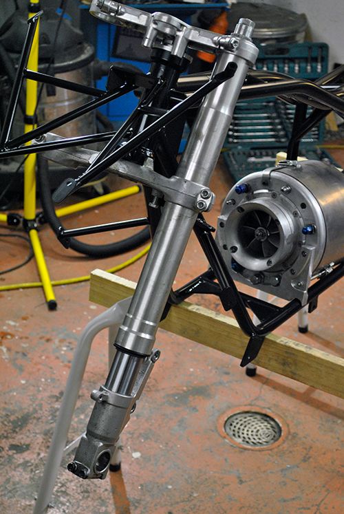 I took the frame outside a while ago to get some decent pictures of it, looks a bit high now without the underhung oil and kerosine tanks. 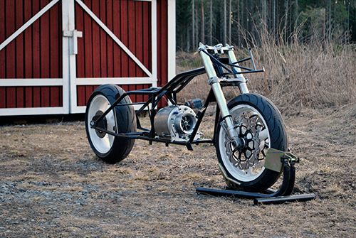 I fitted the gas producer just for the fun of it, I can almost hear it moan "polish me, polish meeeeeeeee......" 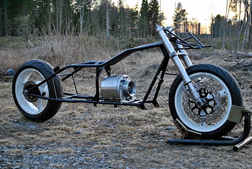 I can´t say that the frame is very wide, the widest part of the bike while riding will probably be my smile.  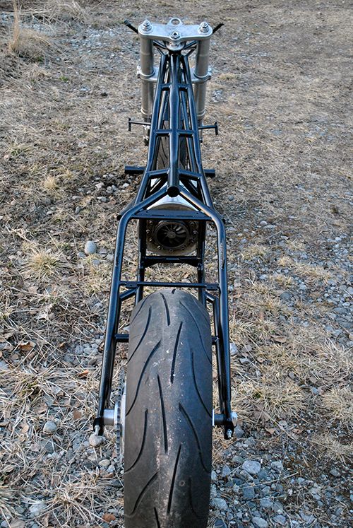 Cheers! /Anders |
|
rythmnbls
Veteran Member
  
Joined: August 2011
Posts: 145
|
Post by rythmnbls on Apr 26, 2014 15:29:37 GMT -5
A bit off topic, but I haven't seen a post from Racket in a few weeks, I hope all is well with him.
Regards.
Steve.
|
|
|
|
Post by Johansson on Apr 27, 2014 16:47:57 GMT -5
After a couple of test ejectors built I have found that they need a large pressure drop to work, the ones I´ve built work just fine until I connect the length of tube that will connect it to the bearing tunnel and then the ejector stops pulling oil. 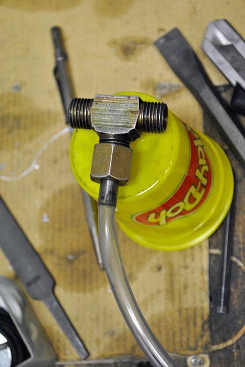 With that figured out I have decided to use the industrial mist oiler after all, the only downside is the plastic internals that won´t take the heat of the bleed air at full throttle but a simple heat sink like a coil of copper tubing should take care of that. 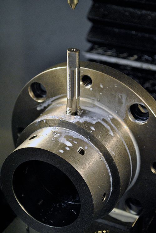 I fitted a hydraulic coupling to the bearing tunnel and tested it at 2 bar air pressure with OKQ8 Wagner 68 gear oil, works like a charm and the amount of oil is fully adjustable on the mist oiler so I think this will work. One other great thing is that a new one can be bought cheap off the shelf in case this one fails me, not a bad thing to have a couple in store when going over seas.  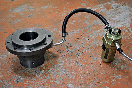 Here you can see the entry hole for the air/oil into the bearing tunnel. 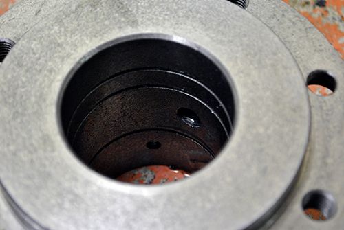 I have to modify the exhaust pipe somewhat since the coupling hits it when I assemble the parts, after that I can start assembling the gearbox with the new ceramic bearings. 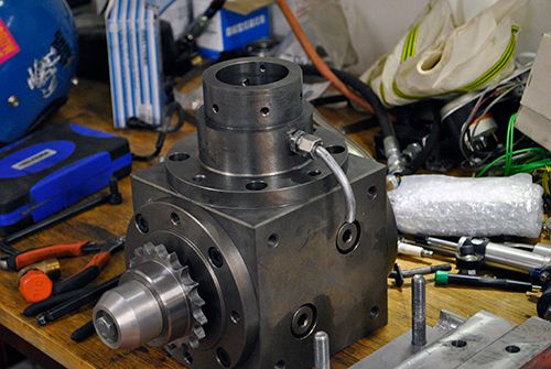 Cheers! /Anders |
|
gidge348
Senior Member
  
Joined: September 2010
Posts: 426 
|
Post by gidge348 on Apr 28, 2014 0:06:31 GMT -5
Hi Anders, I am just wondering how the mister will perform when the gearbox is fully assembled? I was just wondering if it may need a substantially larger exhaust than the inlet so that the pressure does not rise in the bearing housing and stop the oil being pulled? Have found another interesting link www.machinerylubrication.com/Read/799/oil-mist-lubrication that gives a recommended flow based on "moderate operating conditions". Interestingly it recommends oil temp of 130F to 170F so the copper coil heat exchanger sounds like a great idea & seems to recommend higher operating temperatures. Did some quick calculations based on their recommendations. 2 x 6305 C3 bearings with say 10 balls(?) (DR/40)x2 = 12.5 ft3 per minute of mist flow with a maximum velocity of 24ft/min makes the input tube 32mm dia. This is all "best case" and I know 32mm is not going to fit but if there are problems getting the mister to cover evenly, maybe increasing the intake and exhaust may be something to look at? Cheers Ian... |
|
|
|
Post by Johansson on Apr 28, 2014 7:34:23 GMT -5
Hi Ian,
It isn´t really misting but rather dribbling oil into the bearing tunnel, as long as I get oil in there it should work as it drips down onto the rotating shaft and should be thrown outwards to the bearing races.
Do you think I need to mill a pair of slots at 4 and 8 o´clock to assist the oil flow back to the wet sump, or will it flow through the rear bearing even when it is rotating at 30.000rpm?
Will check the link when I get home from work!
Cheers!
/Anders
|
|
gidge348
Senior Member
  
Joined: September 2010
Posts: 426 
|
Post by gidge348 on Apr 28, 2014 22:22:40 GMT -5
Hi Anders, I hope now that John is back on deck he may be able to give some feed back, but I think the main problem is going to be getting the exhaust as large as possible. Or possibly some kind of vacuum arrangement to make sure there is no pressure build up in housing. I think the key to this is no back pressure.
If the oil is dribbling rather than misting I guess is acting more like a squirter than a mister?
Sorry I am having a bit of a problem working out where the inlet and exhaust are, I can see the exhaust is between the bearings, are the inlets on the outside of the bearing so the flow will draw oil through the bearings? (See Fig 4 on the link sent yesterday)
If the rear bearing is spinning at 30K and inlet and exhaust are on either side of the bearing I think it shouldn't be a problem. If it is just pumping a mist/dribble in the centre top and pulling it out the centre bottom, that may be an issue.
Ian...
|
|
|
|
Post by Johansson on Apr 28, 2014 23:20:32 GMT -5
Hi Ian,
I guess you could call it a squirter, the swedish word for it is mister but that is really not that accurate. Not with gearbox oil in it anyway.
I haven´t explained this good enough I see, the fitting you see in the latest pic on top of the tunnel is the inlet and the outlet will be internal through the rear bearing to the main sump of the gearbox. The sump will fill up eventually so I need to check the level once in a while but I can live with that.
When oil enters the space between the two bearings it will pool up until it reaches the bearing races, the bearings will be pumping a bit of air but the oil still has to enter the bearings once the level is high enough. I´ve just decided to fit a piston ring seal to the shaft between the power turbine and the first bearing so no oil can enter the exhaust scroll and catch fire.
Cheers!
/Anders
|
|
|
|
Post by Johansson on Apr 29, 2014 16:43:20 GMT -5
I spent a couple of hours on the power turbine today. 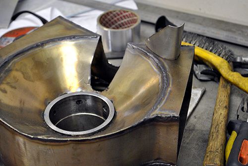 The exhaust housing hit the fitting on the shaft tunnel for the oil/air mix so I had to modify it somewhat to get some clearance. 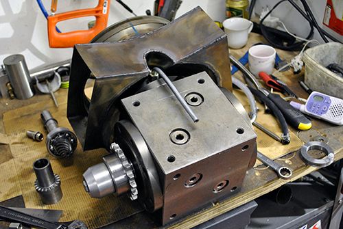 Then I assembled the input shaft housing to simulate a static condition to see if it still would flow oil with the real life air restriction through the bearings, and to my great relief it transported a good amount of oil to the shaft tunnel and after a little while the oil had pooled up to the point that it reaches the ball races.  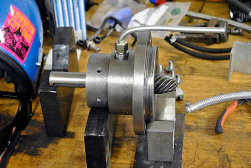 This was at only 2bar air pressure so I will have even better air flow in real life since the P2 will be close to 3bar when racing. I am aware that this is only a static test so I have no idea how it will work with the bearings spinning, but I guess there is only one way to find out.  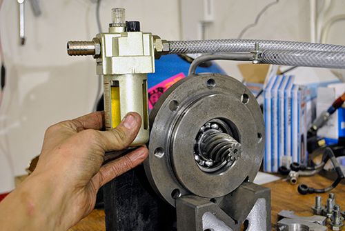 I am also painfully aware of that this solution is far from optimal, but I am cramped both of space and battery capacity and it is by far the easiest way with the least modifications to the gearbox so I will give it a try before I add high pressure lube jets and such. Cheers! /Anders |
|
gidge348
Senior Member
  
Joined: September 2010
Posts: 426 
|
Post by gidge348 on Apr 29, 2014 21:00:57 GMT -5
Ahh, got it now Anders, thanks for that. I think that will be fine, the bearing under the most load will be the pinion bearing and if the input oil has to drain past the bearing to get back to the sump I think it will be fine. I am still a little concerned about the forward bearing with the piston ring seals, I guess by the look of it there is no way to have a drain on the forward side of the bearing? Just to throw another idea into the mix, have you thought of running a race car type diff oil pump to lube the gearbox? www.ebay.com/itm/JOHNSONS-SINGLE-STAGE-REAR-END-OIL-PUMP-MOUNT-PULLEY-LINE-NASCAR-ARCA-/121315907622?pt=Race_Car_Parts&hash=item1c3efdd826&vxp=mtr You could attach this to the chain sprocket or the chain or even the rear wheel. While the engine is running but the bike not moving there is no need for lube in the gearbox, as the speed increases the pump runs faster and shifts more oil. Just fill the wet sump slightly more to cover the oil in the pump and lines and plumb it to your squirter/mister and draw the oil from the wet sump. This may save problems with overfilling and pressurising the gearbox.. Cheers Ian... |
|
|
|
Post by Johansson on Apr 29, 2014 23:01:46 GMT -5
Hi Ian, Unfortunately not, what I can do is to leave the piston rings out for now and let it ventilate into the exhaust housing as well. The narrow gap shaft seal should stop most of the oil and that way I would get a positive air flow through that bearing as well. I have had some belt powered hydraulic pump in mind but the limitations in space made me drop that idea before giving it any deeper consideration, that nascar pump looked like a neat package though. The feature of only pumping oil while the bike is moving would be great though, I´ll keep that idea in mind in case the air dribbler lets me down.  Cheers! /Anders |
|


