joe0545
Member

Joined: August 2010
Posts: 15
|
Post by joe0545 on Oct 2, 2011 18:30:17 GMT -5
Great stuff anders , Well done , and congrats , Good to see the air start is up to the job  Winter  we have to wait till winter for another run , Whats wrong wi tomorrow , heheh, Thanks for taking the time to post all this up with vids n pics and descriptions , much appreciated , |
|
|
|
Post by ernie wrenn on Oct 2, 2011 20:05:30 GMT -5
Way to go Anders.. Amazing how fast it came together..
ernie
|
|
|
|
Post by propellanttech on Oct 2, 2011 22:16:04 GMT -5
Awesome.....Glad to see it worked out well for the first test.
Congratulations, I know your nerves were on edge while doing it for the first time. Looks like you got it right.
James
|
|
|
|
Post by Johansson on Oct 3, 2011 0:05:32 GMT -5
Thanks guys! I did notice that the "purpleing" extended further forward behind the diffuser exit air deflectors , you may need to "adjust" the distribution by having partial deflection over more of the diffuser exits . I will look closer on those marks, when I saw them I assumed they were caused by the propane preheat but closer examination might tell a different tale. I´ll make sure to take lots of pics and measurements while I take the engine apart. The high TOT temps might be partially caused by the lowish P2 , it might improve once up to ~1 bar , if it doesn't you might need to improve the inlet air flow to the engine , theres a fair number of tubes and fan struts that could be causing turbulence at the inducer reducing efficiency. .....................I sorta remember something about NGV throat areas as well , were they a little on the large side ?? The strange thing was that the TOT was steady at 600C until I started to throttle her a bit, then it creapt up to 700C in increments. After the run I realised that I probably ran her a little low in P2 but by then I was out of air so it wasn´t anything to do about it. I can always remove the fan mount for the next test and see if it cause any restriction to the air flow, the NGV throat is slightly larger than optimal but I don´t remember the exact number. Will measure the throat when I disassemble it. |
|
|
|
Post by racket on Oct 3, 2011 3:36:32 GMT -5
Hi Anders
Found your PM to me on the 12 March where you mentioned a 10mm throat compared to the ~9mm I used , that could be enough to increase your temps, and mass flow, which might be a bit much for the 89mm jetnozzle to handle ......................early days yet , might need another few test runs with more data from different power settings before deciding whats what .
Heh heh , any first spoolup that doesn't need parts replacing afterwards , is a very successful spoolup ....................congratulations again , well done :-)
Cheers
John
|
|
|
|
Post by Johansson on Oct 3, 2011 7:44:06 GMT -5
Do you think I should run the engine without the jet nozzle next time to avoid any choking at that point? Yup, really glad it wasn´t reduced to a smoking lump of metal during the hot starts. A larger air bottle next time should give me more time to get her going more smoothly. |
|
metiz
Senior Member
Joined: April 2011
Posts: 297
|
Post by metiz on Oct 3, 2011 12:27:45 GMT -5
Sounds like a winner, tweak it and try again tomorrow, first test drive the day after! XD good stuff man, makes you grinn from ear to ear doesn't it |
|
|
|
Post by stoffe64 on Oct 3, 2011 12:38:07 GMT -5
congratulations Anders,a new turbine engine being born  very nice engine,a very fast build too, i like it! |
|
|
|
Post by Johansson on Oct 3, 2011 14:52:06 GMT -5
Thanks guys! I took the engine apart an hour ago to see what it looks like inside, and found some things that need improvement. 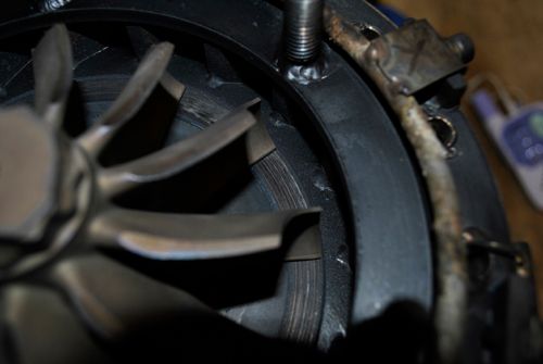 The turbine wheel has rubbed the coating off the NGV housing, this would be caused by the aluminum shaft tunnel expanding more than the turbine shaft and closing the clearance to null. Might very well be a reason why the TOT´s started to climb after acouple of seconds of running. 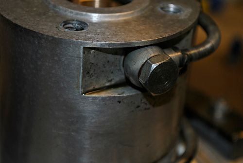 Another thing I found was that one of the banjo oil bolts were not tightened any more and oil was present around it, this would be one of the reasons for the internal oil leakage. 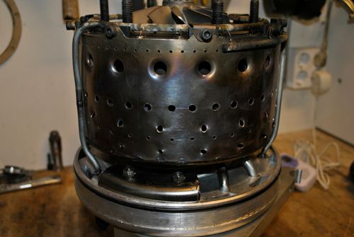 The heat pattern on the combustor was also interesting, at the location of the air deflectors the pattern reached all the way to the combustor lid while it stayed around the secondary/teritary zone everywhere else. 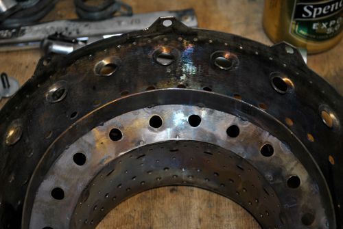 The inner combustor lining was more or less the same all around. 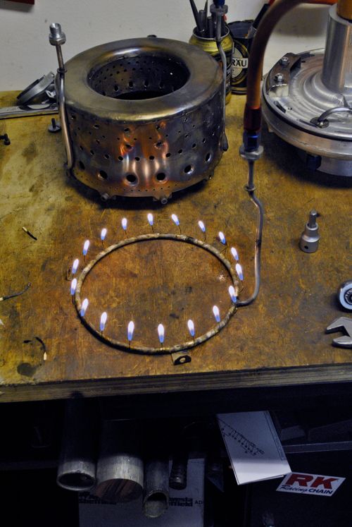 With some propane I found that no syringes were blocked which removes them from the list of possible causes for the creaping TOT. 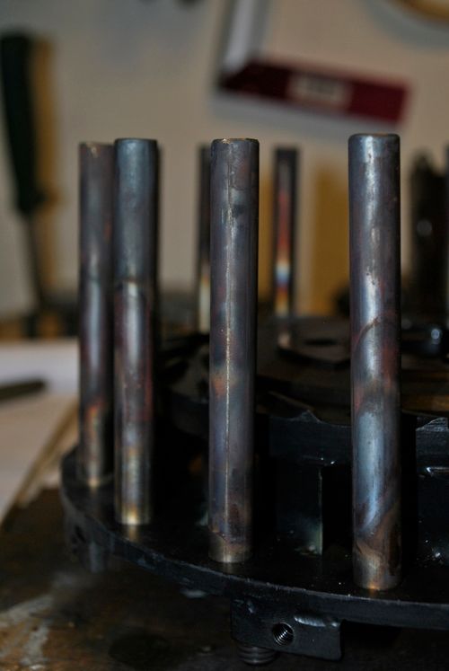 The vapour tubes all had similar heat patterns and no sign of wear, in the next pic you can see that the coating amazingly survive the 1000°C TIT during the hot starts. It seems to stick much better to mild steel than to the stainless NGV vanes. 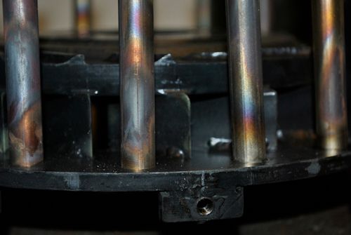 I measured the NGV throats to 10mm wide and 19mm high by the way, how does this compare to your 10/98 John? Cheers! |
|
|
|
Post by propellanttech on Oct 3, 2011 15:41:56 GMT -5
The turbine rubbing will definitely make the temps rise. I would cut a little off the tunnel, and make a little more clearance there (easier than making a longer shaft).
Everything else looks pretty normal other than the combustor which could be a problem. I don't know if Racket had the same heat pattern, so he would have to comment on that.
James
|
|
|
|
Post by racket on Oct 3, 2011 16:06:27 GMT -5
Hi Anders
That rub would have been more than sufficient to get the temps up , the turb wheel is only producing a few foot pounds of torque at idling rpm so even a slight rub will soon cause the rpm to fall and temps to rise as the airflow is reduced . I had a similar rub with FM-1 as I'd set the engine up with minimal clearance between turb wheel and NGV wall to reduce losses , we need to run at least 0.5mm cold clearance , my GT6041 turbo has ~1mm clearance between turb wheel and heat shield as standard , the 10/98 engine isn't much less than that at 0.037" - 0.92mm , we need to also allow for the shaft to move "forward" and minimise thrust washer clearances once air pressure gets to the back of the comp , thrust loads are "forward" and will close the 10/98 clearance between turb wheel and NGV wall to ~0.030'-0.75mm
Another thing you might need to consider is a shaft tunnel heat shield blanket to minimise expansion of the shaft tunnel , I used ceramic blanket with metal sheathing ( baked bean tin ).
With your engine design the air pressure loads on the outer can back wall are taken through the NGV to the shaft tunnel , this may distort your NGV wall and exacerbate the clearance issue, I've always used the slip joint method where there aren't any axial tension loads on the NGV .
The NGV vane material being stainless is probably expanding at twice the rate of the "steel" walls , the ceramic coating probably can't cope with the high expansion rate and cracks.......... LOL, the vanes being made of good material don't need the coating as badly , thankfully the coating is sticking to the walls , looking very promising :-)
NGV throats on the 10/98 average 9.06mm wide , theres a mixture of sizes due to my crap machining of the vane slots in the NGV wall , ............. by ~20mm axial length , for a total area of ~3260 sq mms - 5.05 sq ins .......................I wouldn't be too concerned with your throat area at this stage as the 10/98 temps were quite modest with the 89mm jet nozzle , I think your temp problem was caused by the rub , easily fixed by machining a small recess in the NGV wall for the turb wheel to "fit in " if it wants to, make it 131 mm dia to give a bit of radial clearance as well.
All in all , not much found wrong after its first testrun ..................... heh heh , I've done a lot worse ;-)
Cheers
John
|
|
|
|
Post by Richard OConnell on Oct 3, 2011 21:09:00 GMT -5
Looks good!! The throttle seems a little sensitive, but that doesnt look like it would be to hard to dial in. Looks like your biggest worry is going to be clearance once the temps rise. Aside from a little rubbing, how did the turbine wheel hold up? It looks good, but I cant really see much of the blade's surface area in the video or pictures.
|
|
|
|
Post by Johansson on Oct 4, 2011 0:30:28 GMT -5
Feels good to have found the reason for the climbing TOT so fast, opening up the clearance to 1mm and recoat the surface is a quick fix. Hi Anders Another thing you might need to consider is a shaft tunnel heat shield blanket to minimise expansion of the shaft tunnel , I used ceramic blanket with metal sheathing ( baked bean tin ). I might as well coat the rear of the diffusor plate and the shaft tunnel with the cheramic paint since it won´t reduce the air gap and should provide good insulation for the aluminum. With your engine design the air pressure loads on the outer can back wall are taken through the NGV to the shaft tunnel , this may distort your NGV wall and exacerbate the clearance issue, I've always used the slip joint method where there aren't any axial tension loads on the NGV . Point taken, a fix for this would be to make a steel plate with a bolt circle that fits on the studs welded to the NGV. To that plate I can then fit some sort of turnbuckle that connects to the diffusor plate and holds the engine together. A plate like that would also make the engine housing seal better around the turbine exducer housing, you suggested that I should make one of those earlier John but I stubbornly did it my way. The NGV vane material being stainless is probably expanding at twice the rate of the "steel" walls , the ceramic coating probably can't cope with the high expansion rate and cracks.......... LOL, the vanes being made of good material don't need the coating as badly , thankfully the coating is sticking to the walls , looking very promising :-) Strangely enough the coating has only cracked on the "downside" of the vanes, i.e. the side facing the turbine wheel. As long as they endure I don´t mind. NGV throats on the 10/98 average 9.06mm wide , theres a mixture of sizes due to my crap machining of the vane slots in the NGV wall , ............. by ~20mm axial length , for a total area of ~3260 sq mms - 5.05 sq ins .......................I wouldn't be too concerned with your throat area at this stage as the 10/98 temps were quite modest with the 89mm jet nozzle , I think your temp problem was caused by the rub , easily fixed by machining a small recess in the NGV wall for the turb wheel to "fit in " if it wants to, make it 131 mm dia to give a bit of radial clearance as well. Sounds good, I´ll get right to it! |
|
|
|
Post by Johansson on Oct 4, 2011 0:33:52 GMT -5
Aside from a little rubbing, how did the turbine wheel hold up? It looks good, but I cant really see much of the blade's surface area in the video or pictures. The turbine wheel looks good, a bit of heat pattern on the outer 1/3 of the blades but nothing that isn´t expected from a hot start. It is very difficult to take good pics of the heat patterns unfortunately, I´ll try to adjust the camera settings to see if it makes any difference. |
|
|
|
Post by Johansson on Oct 4, 2011 0:35:34 GMT -5
The turbine rubbing will definitely make the temps rise. I would cut a little off the tunnel, and make a little more clearance there (easier than making a longer shaft). Everything else looks pretty normal other than the combustor which could be a problem. I don't know if Racket had the same heat pattern, so he would have to comment on that. James Elongating the shaft sounds like a quick job...  |
|


 we have to wait till winter for another run ,


