|
|
Post by racket on Oct 4, 2011 3:37:45 GMT -5
Hi Anders The shaft tunnel is also subjected to radiant heat from the inner FT wall as well as being scrubbed by high speed air at >150 deg C at high power settings , even with the ceramic coating I feel it will be picking up a lot of heat , that heat will affect the lube viscosity in the bearings , is there any way you can provide a sheathing of some sort , even a light coloured wrapping will reflect the radiant heat and help protect the all important bearings and their "dynamics", I was fairly concerned about protecting the shaft tunnel , maybe a bit "over protective" , but, better safe than sorry, was my thinking . Trying to "carry" the airloads from the outer can rear back to the diffuser is fraught with problems because of differential expansion rates and is the reasoning behind having "sliding" bits at the hot end with the can fixed at the diffuser , I'm just not certain that at full power with 40psi of P2 in the can and probably somewhere between a half and one tonne of air loading on the rear wall of the can, that the red hot NGV will cope with the tensile loads without distorting to the extent that something rubs or in the worst case actually tears apart ...............I hope it does cope :-) Interesting how the ceramic coating cracked on one side of the NGV vanes , ........maybe the side that is scrubbed by the gases "swirling??" into the NGV causing that side to heat up quicker ..................mmmmm, a strange one that . The more we look , the more little things we find with our engines ........................one thing I should ask , ......did you have any problems with the turb end piston ring seal sticking in its shroud when you disassembled the engine  ........................I've found that my stainless NGV walls have "shrunk" their bores after an engine run resulting in the piston ring being very tightly jammed in the bores and needing force on the turb shaft to "press" the ring out of its bore, and the bore needing to be remachined to size . LOL.......Please do not attempt to elongate your "shaft" ;-) Cheers John |
|
|
|
Post by Johansson on Oct 4, 2011 7:44:47 GMT -5
Hi John, I´ll see what I can do about the shaft tunnel shielding, perhaps I should settle with a layer of coating first and closely monitor the oil temp during the next run. If it increases at a to high rate I will have to fit a secondary shield. But isn´t the front cover bolts used on most engines except for mine exactly that, an airload carrier to the front of the engine? A quick calculation tells me that at 3 bar the load on the NGV vanes will be 930kg´s! Damn that is much, I will have to take my chances and make some sort of clamp that holds the engine together is I want this engine to stay in one piece...  No problems with the rear piston ring seal, it came out almost as easy as during one of the pre-run disassemblys. Cheers! /Anders |
|
|
|
Post by turbochris on Oct 4, 2011 10:15:20 GMT -5
By the way, you looked really good in the suit. Are you practicing for your investors?
|
|
|
|
Post by Johansson on Oct 4, 2011 10:30:28 GMT -5
By the way, you looked really good in the suit. Are you practicing for your investors? No, for the undertaker. ;D |
|
|
|
Post by ernie wrenn on Oct 4, 2011 14:58:03 GMT -5
Did someone say they needed a undertaker? ?? Hearse is ready to run... Suit does look nice, I do have a coffin that size! ernie |
|
|
|
Post by ouchthathurt on Oct 4, 2011 16:17:48 GMT -5
Wow this is awesome with no cnc amazing .You are doing stuff i only dream of. Its tricky doing anything interesting in the uk( too many rules and neighbours)
|
|
|
|
Post by racket on Oct 5, 2011 3:31:16 GMT -5
Hi Anders
When I mentioned problems with taking the load to the diffuser I was talking about some sort of "external" arrangement with turnbuckles , it'd be difficult to get the right "preload" so that at temperature the different expansion rates wouldn't be causing problems , a "standard" arrangement with the can being fixed at the diffuser and the rear of the can being able to "float" axially its not a problem with different expansions .......................LOL, the load on FM-1's 12 inch dia rear wall is ~ 1,700 kgs at a P2 of 40psi , thats why she has such a concave "arse end" , with 15 X 6mm screws at the diffuser each one has >100 kgs of force trying to shear it , it was also this huge force that made it imperative to have a slip joint so that the NGV was "unloaded" .
Good to hear you didn't have a problem with the piston ring seal , it might just be a stainless thing , ............ maybe next time , if there is one , I'd have the seal fitted into a projection of the shaft tunnel turbo style , or a separate seal holder , and not the NGV wall so as to isolate the problem , the seal holder in the freepower unit I made for the latest bike build is a separate unit to the "scroll" .
Cheers
John
|
|
|
|
Post by Johansson on Oct 5, 2011 15:03:09 GMT -5
I still don´t understand how the rear of the engine could be able to float without causing massive leakage of air around the sliding joint... Anyway, I got some work done today so now I have a set of drilled banjo bolts and a more generous turbine/NGV clearance. 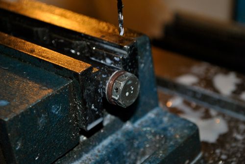 I will drill the oil return plenum bolts later, might need to change them since drilling 12.9 bolts isn´t exactly my idea of fun.  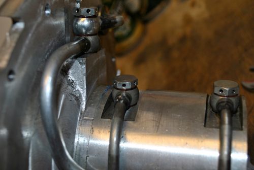 The NGV didn´t fit my small lathe so I had to make an arrangement in the mill for the clearance job. 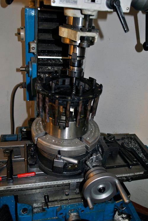 Here is the finished part, the milled surface will get a layer of coating before assembly. 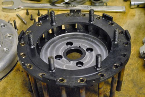 Cheers! |
|
|
|
Post by racket on Oct 5, 2011 18:07:51 GMT -5
Hi Anders
That should take care of the rub :-) ..................LOL, we gotta make some strange jigs at times to machine our bits , I've often been scared stiff that the tooling will jam and the whole lot will be flung out of the lathe, so end up taking 0.1mm cuts at a time and spending half an hour instead of a couple of minutes to do the job , its these "correction" jobs that are the worst , the part was easy to machine in the first place but once other bits are welded on it becomes a different beast to machine :-(
With slip joints the inner "tube" will always run hotter than the outer tube, the inner tube will expand until it contacts the outer tube at which point it then conducts heat to the outer tube and it starts to expand away from the inner tube , an equalibrium is reached where the inner tube is fairly "tight" within the outer tube , there might be a minor leakage but its so small its not a problem , also there is probably some axial loading cause by the friction between the tubes , but overall its a reasonable compromise that is widely used in aircraft exhausts etc
The Solar T62 engine has one between its combustor and the turbine wheel shroud/NGV , heh heh , I copied the FM-1's slipjoint off the T62 I had .
The T62 combustor's slipjoint has a "manufacturers" ID of between 4.852" and 4.856" , replace if exceeding 4.859" dia , the NGV slipjoint OD is between 4.852 " and 4.854" , replace if exceeding 4.855" dia , I'd imagine theres a design clearance of a couple of thou diametrically , just enough to slide the parts together without there being a need for force , the combustor is stainless and the NGV is also some nickle based material with a similarly high expansion rate .
I found with FM-1 that the "designed" slipjoint clearance was "increased" as a consequence of running the engine, making it easier to assemble/disassemble during subsequent pulldowns , the inner tube must have "stretched" the outer slipjoint whilst finding the "equilibrium" point , the slipjoint is ~15mm long axially and I use high temp nickle antiseize on the slipjoint which tends to "boil out" on starting the engine .
A 115mm OD inner slipjoint using stainless steel will expand ~1.25mm with a 500 deg C temp rise , so theres plenty of scope for fairly "rattly" joints that will still seal .
In my "turbochargers" book they recommend a diametric clearance of ~0.005" - 0.008" per inch of tube diameter for stainless slipjoints , thats a HUGE amount and would have meant that FM's slipjoint would work with > 0.5mm of diametric clearance .................LOL, it feels like it has that much after all its "adventures" :-)
Yeh , drilling lockwire holes is a pain in the butt , especially stainless socket headed screws where I always seem to work harden a skin on the stainless , those "black" socket head screws seem to have "hard bits" in them as well , especially just before you break through into the "socket" ...................heh heh , happy drilling :-)
You'll have her back together and ready for another test run by the weekend ;-)
Cheers
John
|
|
|
|
Post by Johansson on Oct 6, 2011 0:15:49 GMT -5
I was very lucky that the number of vapour tubes was dividable by three so the rotary table chuck "teeths" fitted between them, otherwise I would have been in trouble. Interesting info about the slip joints, I never thought about those while designing the engine. I guess I will just have to take my chances and fix the casing at the compressor end as well, if not I believe the welds holding the NGV vanes will break if subjected to the calculated 37.5kg of pull each.  How much expansion can there really be measured from the diffusor to the NGV rear wall? The only parts that get really hot are the NGV vanes and they are only 15mm long axially, there is also the 90 degree "bend" on the lid that will flex a couple of tenths when pressure is applied from the NGV. Ha ha, next weekend I´ll head off with the Speed Weekend gang and celebrate becoming 30 years old so the only testing that will be done then is finding out how drunk you can get in a sauna without getting thrown out. ;D |
|
|
|
Post by racket on Oct 6, 2011 3:37:38 GMT -5
Hi Anders
Sounds like a good weekend coming up , the big three O , a milestone in ones life , enjoy :-)
Yeh , some diffuser screws through the combustor wall will be a bit of insurance, there should be enough flex in the rear wall to cope with axial expansionary changes .
Its a hard one trying to workout the various expansions , just so many variables , the outer stainless can will expand different lengths depending on the T2 , whereas the NGV vanes will have less relative changes in length but a greater initial expansion , the shaft tunnel will be influenced by T2 but maybe the lube flow will stabalise metal temps .....................a good case for having some sort of sliding joint , the axial turbine'd micro engines simply bolt the NGV to the rear wall and let it slide on the shaft tunnel , we unfortunately can't because of the inflow wheel.
Enjoy the Birthday :-)
Cheers
John
|
|
|
|
Post by Johansson on Oct 6, 2011 5:41:12 GMT -5
Sure is, fortunately I don´t feel like I have wasted my years so far so no 30-year crisis for me.  Yeh , some diffuser screws through the combustor wall will be a bit of insurance, there should be enough flex in the rear wall to cope with axial expansionary changes I meant fastening the engine casing in the compressor diffusor cover as well as with the 6 bolts welded to the NGV. (perhaps you did as well, I got a bit uncertain about the sentence "through the combustor wall". You didn´t mean to fit screws through the casing and combustor outer wall and to the NGV front wall just before the 90 degree bend into the vanes did you?) Sorry for not understanding, we have some company meeting all day and my head is already starting to feel numb...  |
|
|
|
Post by turbochris on Oct 6, 2011 8:46:47 GMT -5
What was that? you want to get drunk and see how many sauna's you can get thrown out of? Have fun, you have a lot of skill and wisdom for a 30 year old, take advantage of it!
|
|
|
|
Post by Johansson on Oct 6, 2011 15:53:37 GMT -5
No no no, not want. Going to is the right word.  Anyway, I drilled all internal bolts today and made a drain line from the engine cover so I easily can check so there isn´t any pooled up liquid inside the engine. 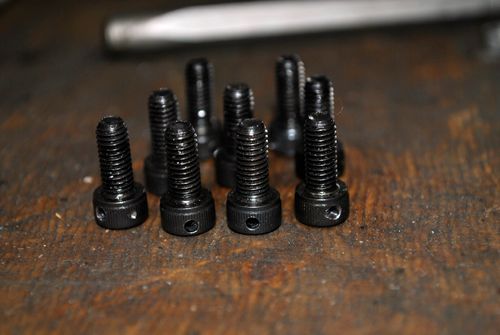 The return oil plenum with drilled bolts. 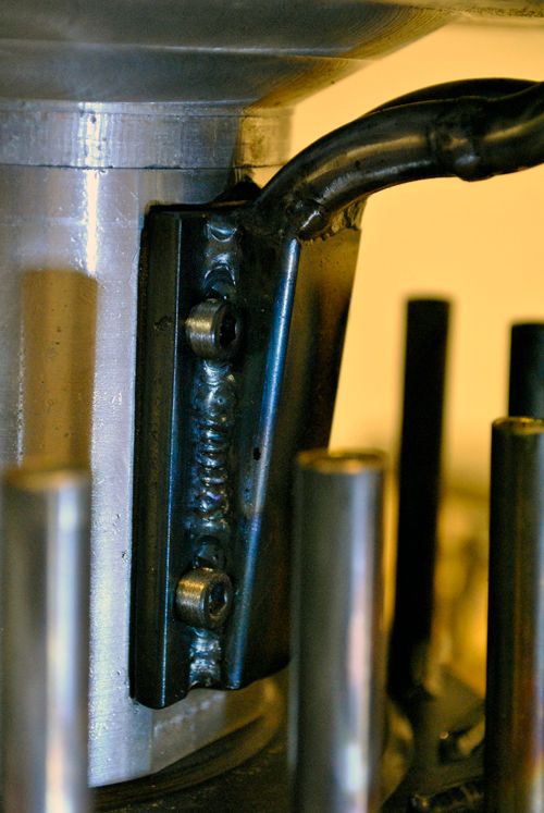 A banjo bolt mounted to the lowest point of the engine cover. The crappy welds is because I didn´t want to put more heat into the stainless cover than absolutely necessary. 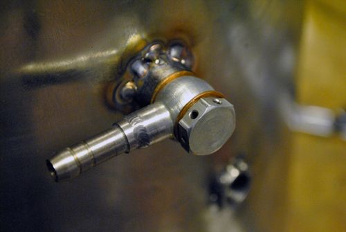 I will use a pneumatic solenoid instead of a ball valve since I would most likely forget to close a ball valve in the heat of the battle, a spring loaded push button will manouver the solenoid so it only opens when I have my thumb on the button. 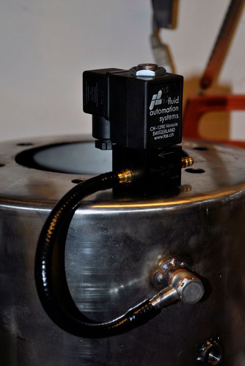 Cheers! |
|
|
|
Post by racket on Oct 7, 2011 0:06:28 GMT -5
Hi Anders
Through the outer can wall and into the diffuser/front cover :-)
The drain valve can be made so that a light spring opens the valve when there is little P2 pressure but as soon as the P2 rises the out flowing air automatically closes the valve and the P2 keeps it closed until shutdown when it reopens as P2 drops to ambiant .
LOL, you're gunna have to get some high silver content silver solder for fitting bits into the stainless steel outer can , it does a nice job with minimal distortion .
Happy drinkin' :-)
Cheers
John
|
|


 ........................I've found that my stainless NGV walls have "shrunk" their bores after an engine run resulting in the piston ring being very tightly jammed in the bores and needing force on the turb shaft to "press" the ring out of its bore, and the bore needing to be remachined to size .


