|
|
Post by pitciblackscotland on Nov 19, 2011 7:29:38 GMT -5
Awesome video Anders thanks for sharing with us -  Cheers, Mark.. |
|
|
|
Post by Johansson on Nov 20, 2011 14:38:05 GMT -5
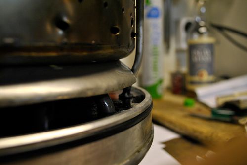
Thanks! I owe so much to Racket for his help throughout the build so most of the praise should be directed to him and not me. I removed the casing yesterday and found nothing alarming inside, some coating on the backside of the diffusor plate had worn off from the air flow passing by so that was the source for the sparks during the run. 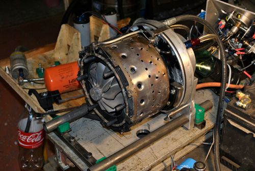 The area where the coating had come off, I didn´t sand blast the aluminum parts since the coating there was only supposed to shield the aluminum from some radiant heat. 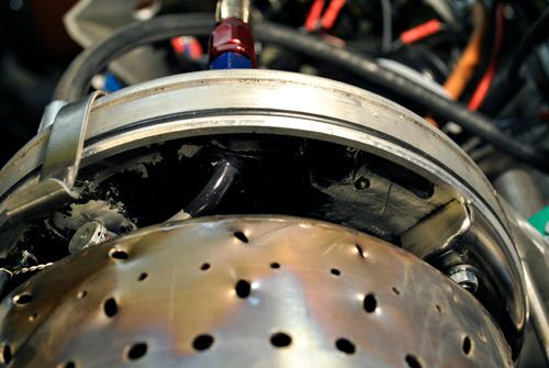 The vanes in the NGV have no coating left on them in the throat area but that doesen´t matter since they are made from SS2368. 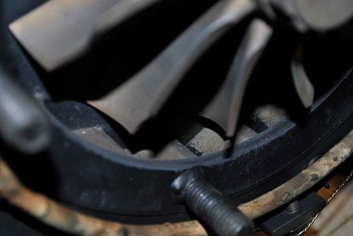 Here is some food for thought, the heat pattern on the combustor starts in the secondary zone and continues all the way to the NGV. The section behind the air deflectors is blue all the way from the CC lid to the NGV. Perhaps I should remove the deflectors I use now and weld a 360° deflector ring on the CC lid that splits the air stream in two? 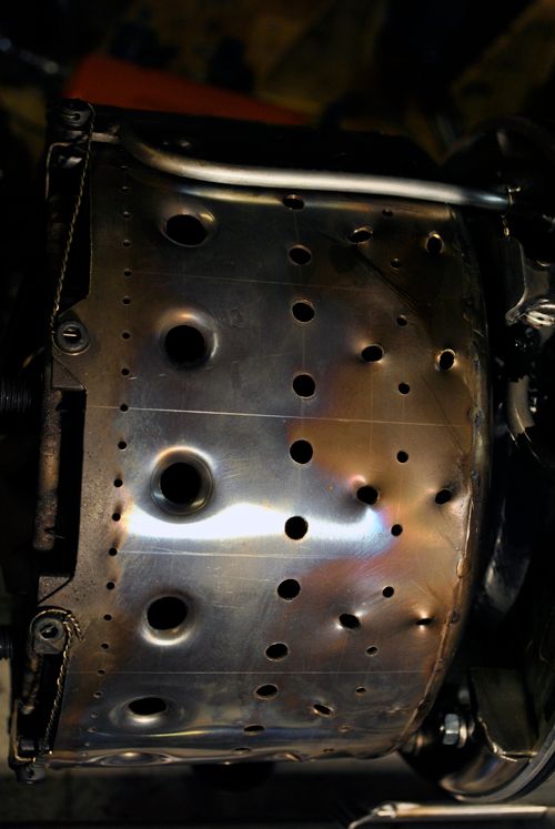 Cheers! /Anders |
|
|
|
Post by racket on Nov 20, 2011 16:37:51 GMT -5
Hi Anders
Lookin' good :-)
The flametubes still "shiny" so no burnt metal , just radiant heat colouring , looks just like a micro flametube should , with the front uncoloured and the rear a nice purple , the extra colour behind the air deflectors is a concern though it could simply be leftover colour from those initial spoolup difficulties that we all experience getting a new engine to fire up .
Have you been able to check the inner wall for heat damage ?? ..................to see if the air deflectors are doing their job , they should be , but it never hurts to double check .
..............LOL, I've heard about guys burning out their inner walls when they didn't ;-)
Ideally a 360 degree deflector , but its hard to make for our application with all the plumbing going through it , unfortunately we need to make compromises :-(
You should be very happy with the way she's performing ..............its all a learning process , some things work , others don't and need modifying , just a matter of muddling through :-)
Cheers
John
|
|
|
|
Post by Johansson on Nov 21, 2011 12:23:39 GMT -5
Ok, so I should be satisfied with the combustor then? Good to hear, I compared it to the kick CC where the pattern sits perfectly in the top of the can but then it is a good 10-15 times larger than the annual combustor for the JU-01...  Haven´t removed the combustor yet to inspect the inner wall, but as far as I can see there is no damage done to it. I figured I could remove the two deflectors and make a stainless hollow cone that is welded to the CC lid outer edge and reaches into the air stream going from the diffusor outlets into the space between the CC and the engine housing, it will steer a part of the air inwards past the CC lid and to the shaft tunnel. I can draw it up for you if my explanation wasn´t clear enough. I am very happy with the engine performance at this point, with a tachometer, a jet pipe pitot tube, a fuel pressure gauge and some minor mods I have in mind it will be very interesting to run it again! Cheers guys! |
|
|
|
Post by Johansson on Nov 21, 2011 15:47:39 GMT -5
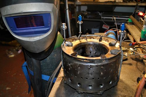
I took the engine apart today to check the CC inner wall and some other stuff, so now the test bench is empty again. 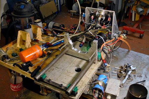 The coating on the aluminum parts didn´t stick very well at all, but I will leave it where it is since it probably will block some of the radiant heat anyway. 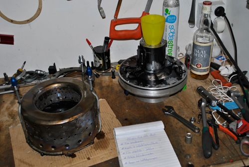 The heat pattern on the inner wall is very even and no signs of overheating can be seen, unfortunately the same can not be said about the lid and outer wall with two distinctive heat marks on the lid just behind where the air deflectors are placed. 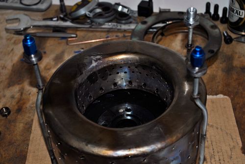 I am seriously considering making another kind of deflector that directs a part of the air coming from each diffusor slot instead of directing all of the air from a few slots, I don´t know if it even is a problem but there was a hotspot on top of the jet pipe that might have been caused by this. Cheers! |
|
|
|
Post by racket on Nov 21, 2011 22:08:34 GMT -5
Hi Anders
Inner wall looks good , still some shine on the metal so no burning :-)
If you make a different air deflector keep in mind the need to provide radial straightening "vanes" so that the air going to the centre of the engine doesn't have any tangential swirl component , this was one of the reasons why I made "individual" ducts for each of the diffuser outlets on the 10/98 engine , I didn't mind a bit of swirl with the air going along the outer wall but I was careful about that going to the centre .
On the 9/94 I installed a deflector on every second diffuser outlet to lessen the chances of just what you're experiencing with a couple of large blocks , ideally we want to split the flow from all diffuser outlets nice and evenly but its difficult to achieve in the small space available with all those pipes .
Cheers
John
That heating of the front wall sorta indicates the possibility of hot gases "exiting??" the FT outer wall holes into the "low pressure" area in the wake of the deflectors , the front wall is continually being sprayed with a cooling mix of air and fuel so shouldn't have any "colouring"
|
|
|
|
Post by Johansson on Nov 22, 2011 1:03:57 GMT -5
I will have to think it through before I start modifying anything, the 360° deflector will be very easy to make but it will be more difficult to predict just how much air it is deflecting.
Another option would be to drill some holes in the deflectors I use now to get rid of the low pressure zone behind them, but that would of course lower the rate of air steered towards the inner wall so I don´t know if it is such a good idea...
|
|
|
|
Post by racket on Nov 22, 2011 3:39:58 GMT -5
Hi Anders
If you can fit a 360 degree deflector thats the best method but it must have radial straightening vanes to be certain theres no swirl , be careful about the various expansion rates though .
Cheers
John
|
|
|
|
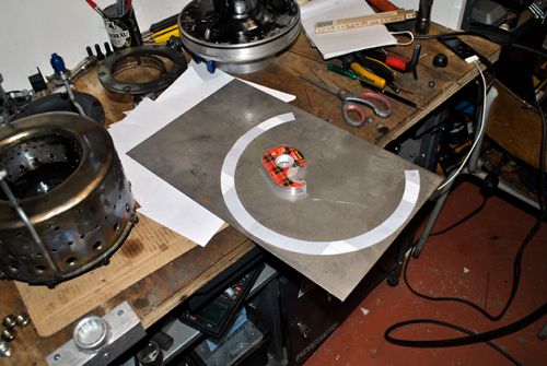
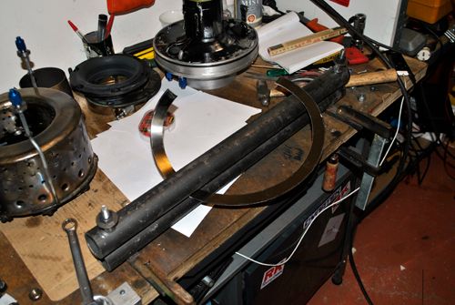
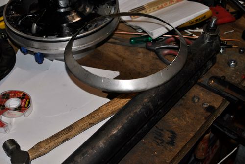
Post by Johansson on Nov 23, 2011 0:48:05 GMT -5
I took some measurements yesterday and printed the cone layout so in a day or so I should find time to make the new deflector ring, my gut feeling tells me that it will work fine. |
|
|
|
Post by Johansson on Nov 23, 2011 16:52:07 GMT -5
|
|
|
|
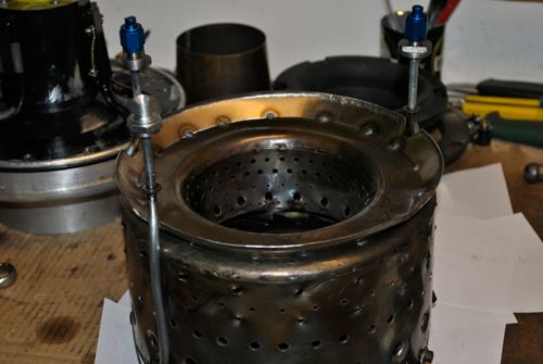
Post by racket on Nov 23, 2011 21:16:00 GMT -5
Hi Anders
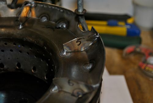
Nice job :-)
I think you might need more straightening vanes, even if they're only "part vanes" at the outer diameter , ideally we need "channels" about as wide as they are deep to effectively "capture" the air and direct it radially inwards , if theres too much "circumferential" width between vanes there most likely will still be some swirl .
Could you slot the ring and weld in small sections of vane , you could have them protruding into the outer airflow a bit as well .
One problem you may have with a welded on ring is the varying diameter between the front wall of the FT and the ring diameter as temperatures vary , I'd be inclined to split the ring into a number of segments once all the vane welding has been finished ......................some tip shrouded turbine wheels have the rotating shroud/labyrinth seal split in several positions around the outside to reduce expansionary stresses .
What sort of "division " have you between outer and inner airflows ??
Cheers
John
|
|
|
|
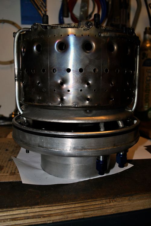
Post by Johansson on Nov 24, 2011 0:50:51 GMT -5
I´ll try to fit some vanes with reduced height between these ones. Slotting the ring might be needed, but do you think I can run it once first to see if it even is a problem that needs fixing? I thought about the temp difference between the ring and the combustor lid, but figured that since the lid doesen´t get any colour at all (except for the spots caused by the previous deflectors) it shouldn´t vary too much in diameter. Might be wrong though. The new deflector should steer 1/3 of the air to the inner wall and let 2/3 pass by it, it can be adjusted later with a pair of pliers if less or more air needs do be deflected. Another thing I have done that might improve combustion is that I have tweaked the syringes a bit so they blow the fuel at a steeper angle towards the vapour tube wall, earlier the angle was very shallow for some syringes which means that the fuel might have traveled a fair bit down the tubes before even hitting the wall.  |
|
|
|
Post by racket on Nov 24, 2011 3:26:58 GMT -5
Hi Anders
Yeh yeh , give her a run as is , .....LOL, I'm just a bit paranoid after burning out the 10/98's inner wall :-)
What percentage split of total FT hole area is there between inner and outer holes ?? ...............is it roughly the same 1/3rd - 2/3rds as the deflector should provide ??
With my syringe needles I bend a ~45 degree angle on the end of the injector so that it squirts against the wall of the evap within ~10mm of the inlet , I made up a piece of "tooling" so that all my injectors are the same , even to the orientation of the bend in relation to the "sharp end" thats fitted into the manifold , and its relationship to the fuel flow direction , so that there'd be consistency and hopefully an even distribution of fuel around the flametube
With my FM-1 flametube , it was ~11 inch diameter, and the lower injectors flowed more at idle due to the "hydraulic head" difference between them and the upper injectors and was one of the reasons why I had to "sleeve" the original syringes with a smaller syringe needles to increase fuel pressures and reduce the differences between the upper and lower injectors .
Cheers
John
|
|
|
|
Post by Johansson on Nov 24, 2011 14:29:46 GMT -5
Will do so, the syringe mod along with the new deflector should show some results on the temp gauge. Hopefully for the better... You should know, after all it was you who drew up the combustor for me.  Just teasing, the percentage is pretty close to 33% inner hole area with 2450mm2 compared to the outer wall + vapour tube area of 4700mm2. How much was the TOT affected by this hydraulic head difference, with the relatively low temps at idle one can perhaps live with a slight hot spot at the bottom of the NGV? Cheers! (By the way, the forum is strangely quiet these days. What are the other builders up to one can wonder...  ) |
|
|
|
Post by racket on Nov 24, 2011 16:48:28 GMT -5
Hi Anders
Yeh , the Forum has been a bit quiet lately , LOL......guess they're all too busy constructing stuff to sit at the keyboard ;-)
When I constructed FM-1 I spent a fair bit of time checking fuel flow rates etc , I actually had separate plastic tubes from each evap to individual identical glass receivers ( 15 used coffee bottles) and checked flows at differing fuel pump delivery pressures and found that with idling fuel flows at ~0.5psi pressure drop there was a ~50% difference in fuel flow between the top to bottom injectors ( 0.9mm OD syringes) , once fuel pressures were increased by the use of smaller bore injectors ( 0.65mm OD syringes) the "hydraulic head" became a smaller proportion of overall idling fuel pressure drop of ~2 psi and reduced the variation to acceptable limits .
With idling P2 pressures of say 5 psi , fuel pressure should be ~7 psi
Cheers
John
|
|


 )
)