metiz
Senior Member

Joined: April 2011
Posts: 297
|
Post by metiz on Nov 26, 2011 13:16:07 GMT -5
Hey Anders Still rocking the cone designer I see  How do you manage to get even those big, thin cones so round the first time? I use the same bending tool as you but my cones always end up oval and crooked. After I weld them I still have to beat the shit out of 'em to get them round again. As always, nice work. Build more, sell them, get rich! |
|
|
|
Post by Johansson on Nov 26, 2011 13:59:44 GMT -5
Lots of practice I guess, it gets easier every time I make one and as you know I made a fair number of stainless cones during the Thunderchine build... |
|
|
|
Post by Johansson on Nov 26, 2011 15:21:50 GMT -5
Hi Anders Yeh , the Forum has been a bit quiet lately , LOL......guess they're all too busy constructing stuff to sit at the keyboard ;-) When I constructed FM-1 I spent a fair bit of time checking fuel flow rates etc , I actually had separate plastic tubes from each evap to individual identical glass receivers ( 15 used coffee bottles) and checked flows at differing fuel pump delivery pressures and found that with idling fuel flows at ~0.5psi pressure drop there was a ~50% difference in fuel flow between the top to bottom injectors ( 0.9mm OD syringes) , once fuel pressures were increased by the use of smaller bore injectors ( 0.65mm OD syringes) the "hydraulic head" became a smaller proportion of overall idling fuel pressure drop of ~2 psi and reduced the variation to acceptable limits . With idling P2 pressures of say 5 psi , fuel pressure should be ~7 psi Cheers John So my 0.7mm OD syringes shouldn´t cause any problems then. I´ve ordered a fuel pressure gauge and should have it by next weekend. I remember seeing a pic of your flow test assembly and thought to myself that it looked cool, would probably raise an eyebrow or two if someone came by while one was doing such a test. |
|
|
|
Post by racket on Nov 26, 2011 16:59:45 GMT -5
Hi Anders
Nope , no problems to be expected with your 0.7mm injectors :-)
Heh heh , I guess it would have looked a bit strange decanting blue kero into coffee jars , its was good to see how the individual jars filled up , there was minor variations even between adjoining injectors that couldn't be accounted for by any hydro head influences , I guess that small differences with injector inlet conditions/orientation/whatever made for a small change of a few percentage points in flow ....................it gave me some good insights into what was going on though .
Cheers
John
|
|
|
|
Post by Johansson on Nov 29, 2011 13:35:40 GMT -5
Good to hear. |
|
|
|
Post by Johansson on Dec 6, 2011 18:20:27 GMT -5
I´ve managed to get some work done on the engine today, so now the core of the engine is back together again. 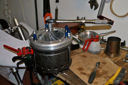 I used a heat resistant gasket between the engine cover and turbine housing which didn´t look very good after it had been removed a couple of times, so I decided to rebuild the engine cover so that I can do without the gasket. 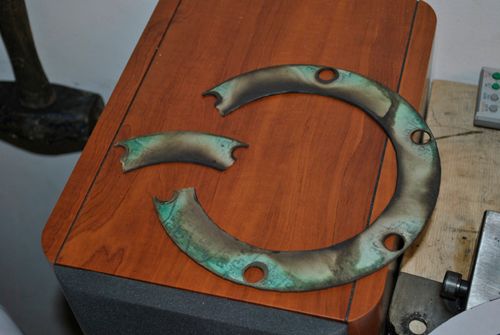 A 5mm thick stainless sheet was used to make a flange identical to the old gasket. 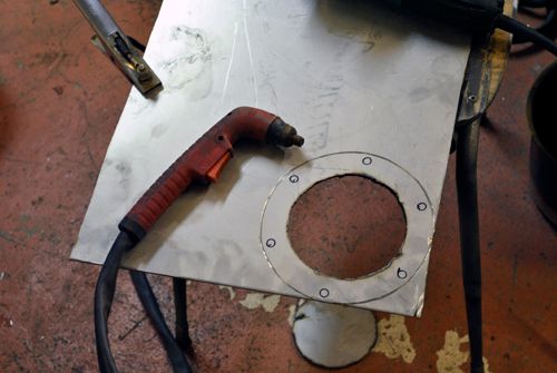 The reason why I haven´t had time to do anything to the engine lately is visible in the upper left corner, I fitted a digital readout to the mill last week that my mother gave me as a birthday present. Much better than socks and lottery tickets! 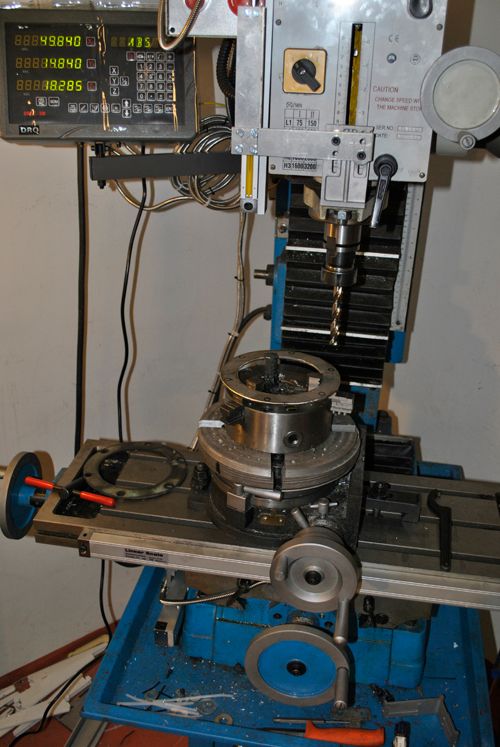 Done! 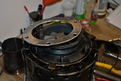 I cut the old bolt circle out with the angle grinder. 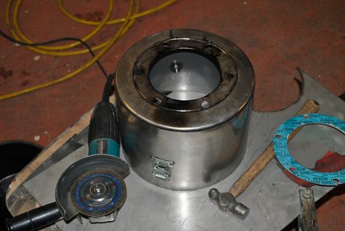 Tadaa! 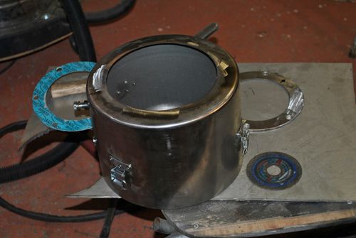 Here are the flange and cover fitted on the engine again awaiting to be welded together, hopefully I will find time to do it tomorrow. 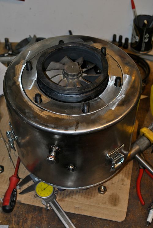 Cheers! |
|
|
|
Post by racket on Dec 7, 2011 0:31:57 GMT -5
Hi Anders
Development progressing nicely :-)
Cheers
John
|
|
|
|
Post by Johansson on Dec 7, 2011 1:46:24 GMT -5
Yup, when I am finished it will be a quite different engine than the one I started out with. |
|
|
|
Post by Richard OConnell on Dec 7, 2011 11:11:51 GMT -5
Very nice. |
|
|
|
Post by Johansson on Dec 7, 2011 16:52:24 GMT -5
The engine housing is welded now, it looks like crap since I had to keep the heat as a minimum to avoid warping of the flange. 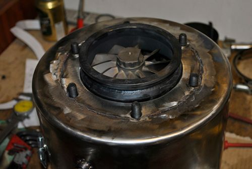 With the internals of the engine finished I could assemble the engine and fit it to the test bench again, the rev counter and some other stuff needs to be fixed before the next test run but at that can be done with the engine in place. 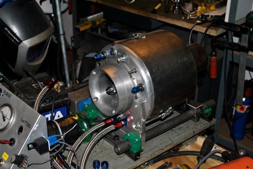 Anyone willing to guess what this will be when it is ready? ;D 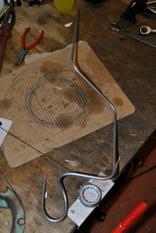 Cheers! |
|
smithy
Member
Joined: August 2010
Posts: 31
|
Post by smithy on Dec 7, 2011 17:50:04 GMT -5
Water injection maybe???
BS
|
|
|
|
Post by Johansson on Dec 8, 2011 0:03:01 GMT -5
Nope. It will be a pitot tube for measuring the absolute pressure in the jet pipe, John suggested I should take that reading since it is needed for the power turbine calculations. |
|
|
|
Post by racket on Dec 8, 2011 16:47:07 GMT -5
Hi Anders
Thats a big one ;-)
Try and position the inlet about 15-20mm in from the sidewall of the duct so that its receiving the full blast of the gases exiting the exducer ...................should producer 10 - 12 psi of total pressure if all goes well ...................maybe even more on one of your freezing cold Swedish winters day ....................I'll have to some calcs to see what happens with a minus 10 C ambiant ..................I use a balmy 15 deg C normally , turbo maps are corrected to a 25 deg C ambiant , so plenty of scope for increases , ~13 % just on denser air , that'll mean a flow of ~2.83 lbs/sec not the 2.5 designed ..................then theres the reduction in power required for compression ...........mmmmmm, looking interesting :-)
Cheers
John
|
|
|
|
Post by Johansson on Dec 9, 2011 3:21:35 GMT -5
Will do! |
|
smithy
Member
Joined: August 2010
Posts: 31
|
Post by smithy on Dec 11, 2011 17:37:52 GMT -5
Hi Anders,
Really enjoying your build info and photos, keep 'em coming..!
I wish I had some of your equipment in my little workshop.
Great workmanship and interesting ideas..!
Cheers,
Smithy.
|
|


 How do you manage to get even those big, thin cones so round the first time? I use the same bending tool as you but my cones always end up oval and crooked. After I weld them I still have to beat the shit out of 'em to get them round again. As always, nice work. Build more, sell them, get rich!


