|
|
Post by Johansson on Jan 14, 2012 2:24:24 GMT -5
A thought John, how would the engine react to overly large tip clearances for the compressor wheel? The temps would rise if the turbine wheel clearance is larger than optimal, but would the PR at different rpm´s change if the scenario is applied to the comp wheel? The reason I ask is because I had to schim the comp housing a bit during the last run since the comp wheel rubbed the housing after the engine had been preheated, so in case I won´t get the same PR at 66.000rpm as you I have a reason for it.  |
|
|
|
Post by racket on Jan 14, 2012 2:51:59 GMT -5
Hi Anders
LOL, .....Just how much extra clearance ,....... I've found that 0.3 mm isn't too bad for our comps , they'll tend to "move forward" under the air loads on the back of the comp and reduce any axial bearing clearance . With a 10mm tip height on our comps , a 0.3mm clearance is only a few percent, well within reason .
You can always re-shim the comp to get clearances a bit tighter , at times I've added a thin shim between comp and seal holder .
Turbos have fairly generous clearances because of the "brass bushes" , I setup my 9/94 with only ~0.15mm axial clearance on the blading because of the ball races .
Cheers
John
|
|
|
|
Post by Johansson on Jan 15, 2012 4:21:06 GMT -5
The thing is that I´ve found that the comp shroud radius isn´t perfect, within a tenth or so but it could be better. After a prolonged preheat during the last run I got a rub about halfway down the radius but with a 0.2mm shim it runs free. After todays run I will put some more effort into getting a perfect fit throughout the entire radius so I can tighten the clearance more. Keep yer fingers crossed! |
|
|
|
Post by Johansson on Jan 15, 2012 23:20:40 GMT -5
Bugger, minor setback today. The compressor wheel nut had worked its way lose and disaster was inevitable, I cannot have torqued it down enough. Don´t think it is repairable... ;D 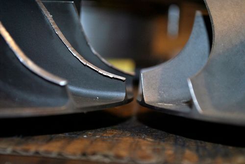 The shaft play felt alarmingly wobbly at first but after disassembly I compared the worn bearings to new ones and except for some wear marks and discolouring on the rear bearing they are identical to the last 0.01mm. 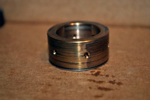 Needless to say I will still fit a new set of bearings when I put the engine together again, the thrust bearing survived without any measurable damage to it but I´ll change that one too just in case. Here are the data we managed to collect before the disaster struck, the temps are looking good and the engine is very responsive to the throttle so with a new compressor wheel and some touch-up work on the comp and turbine covers it´ll be ready to run again. 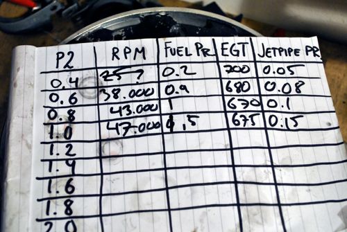 Some heat soak on the shaft after a couple of hot runs due to an almost empty scuba tank. With a filled one it started instantly as you can see in the video. 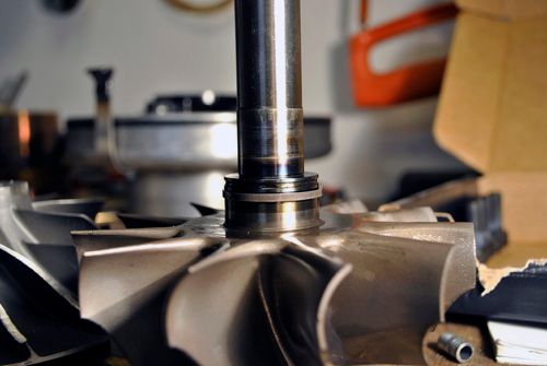 The new air deflector did its job since the combustor is evenly coloured now and no hot streaks are visible in the exhaust, so it wasn´t all bad today. Cheers! |
|
|
|
Post by Richard OConnell on Jan 16, 2012 1:17:25 GMT -5
ouch that sounded nasty.. did it stall completely? and no signs of serious heat damage?
|
|
|
|
Post by racket on Jan 16, 2012 3:46:12 GMT -5
Hi Anders
You were lucky not to have damaged the turb wheel :-)
Your data sorta indicate a mass flow slightly to the high side as P2 is a little "low" for the rpm being used , and temps are on the high side of where I'd expect them to be for the sized jet nozzle being used ( 89mm ??) , nothing is excessively "off design" but probably those slightly larger NGV throats are the culprit , it'll be interesting to see how the higher P2 data goes.
Did a few rough numbers and they don't work out :-( ...............you should have more P4t , ~0.3 bar at your 2:1 PR at 47,000 rpm .................with ~60 lbs of thrust??
Cheers
John
|
|
|
|
Post by Johansson on Jan 16, 2012 7:29:23 GMT -5
Hi John,
The turbine wheel has some minor rub marks but nothing that makes a difference.
To compensate for the rather large jet pipe probe I opened the jet nozzle up to 90mm before this run, I figured that I could always make a tighter one later if it runs too cold.
Before I run her again I will spend some time getting a perfect fit for the comp and turbine wheel, it shouldn´t be far off as it is but I want to make sure that the high TOT isn´t caused by extensive tip clearance.
What jet pipe pressure would you expect at those revs? I will double check the gauge and line so there isn´t any leaks or so next time I head to the shed.
Cheers!
/Anders
|
|
wolfdragon
Senior Member

Joined: April 2011
Posts: 287
|
Post by wolfdragon on Jan 16, 2012 11:09:55 GMT -5
So what won, the compressor wheel or the compressor housing? Or did they both lose?
With a spare comp wheel sitting right there... order another spare and use that one.
Yes that comp is repairable BUT (and this is coming from a fellow TIG welder that actually finds thin aluminum "fun") building the blade height back up, with zero voidspace, and minimal heat to avoid making the HAZ too large will be a pain, especially with the odd geometry. Then you would need to get the height back in contour and then thin out weld to match what the leading edge should be. Then you get to high speed balance it all over again.
With spares readily available, just consume the spares...
|
|
|
|
Post by turbochris on Jan 16, 2012 13:09:51 GMT -5
I had that happen on the TV91 I used in Junkyard wars. The compressor nut should have been a left handed thread. Sounded just like yours when it got loose. it f'd the shaft up on mine though....
|
|
|
|
Post by racket on Jan 16, 2012 16:55:28 GMT -5
Hi Anders
Your temperatures are running ~100 deg C hotter than the 10/98 with its 89mm jet nozzle, you might be able to check the CD video I sent you for the differences at different rpm , at 46,000 rpm I was only running ~525 C whereas you are up at 675 C a 150 deg C diff, I was running too cool , you are perhaps a tad too hot for so early in the development , but probably closer to the desired end mark .
With your 47,000 rpm figures , the TV94 map gives a PR of ~2.05 :1 in the middle of the highest effic. island at ~85-90 lbs/min , but only a 2:1 at a higher flow of ~100 lbs/min , I assumed a 76%effic , but this could be a tad higher , and an ambiant air temp of 0 deg C -273K , this looked about right by the amount of snow outside :-)
At 2:1 PR there should have been a temp rise of ~78 deg C ( T2 of 78 C) so a temp drop thru the turb of ~67 deg C requiring a PR across the turb of ~1.45 :1 at 80% effic from ~1020K .
Assuming a ~5% pressure drop across the FT and a PR of 1.9 going into the turb stage , it should have left a PR of ~1.3 in the jetpipe . ................0.3 bar on your total pressure pitot g/g.
If you were able to measure thrust whilst obtaining data , its easy to cross check the figures to get mass flow , the TOT readings can be reasonably accurate and assuming a nozzle efficiency of 90% we can workout the velocity from temp and pressure , and after doing a density calc the theoretical mass flow thru the nozzle area , if the calcs come out within 5% then they're good enough considering the measuring tools we use .
You could check your P4t g/g by hooking it up to a long length of plastic tubing filled with water and check pressure vs water height/column.........................all the low pressure gauges I've had never seem to read correctly ....................its hard to get a 1 bar gauge :-(
Cheers
John
|
|
|
|
Post by Johansson on Jan 16, 2012 17:41:37 GMT -5
I might have found a reason for the rather high temps, I measured the compressor inducer tip clearance today and found that it is 0.5mm compared to the 0.3mm you ran on the 10/98. Turbine exducer clearance is 0.6mm. The axial clearance is fully adjustable so I will make it 0.3mm for the comp exducer, what do you suggest for the turbine inducer? 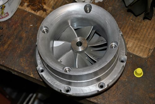 For the comp cover I have the option of welding in material and reprofile it if you think it is needed, I put some effort into making the radius as good as possible so I should at least be able to tighten the axial clearances on the two housings some. 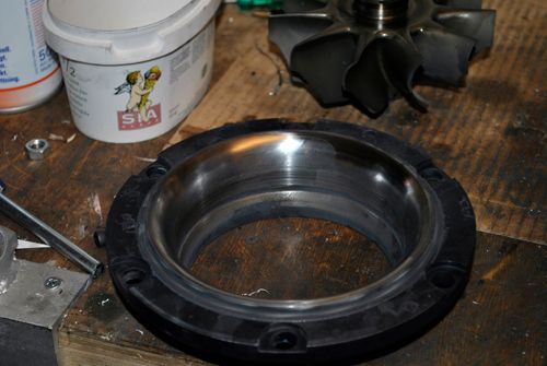 I also measured the turbine shaft and to my relief I found that it ran true without any signs of being bent. I had to remove some aluminum that had stuck to the shaft where the compressor wheel sits, when the shaft spun inside the comp wheel some material must have come off. 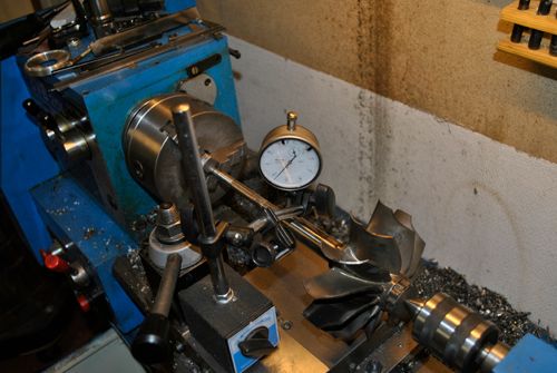 It was a bit difficult to remove the damaged comp wheel, had to heat the wheel with the propane torch while applying pressure in the hydraulic press before it snapped loose from its friction welded state. I installed a new set of bearings and started to assemble the engine again, the oil bolts were torqued to 8Nm and thread locked but I found that they were quite loose so I increased the torque to 12Nm this time. I don´t dare to go much higher since destroying a thread in the aluminum housing would be a disaster...  I will try to check the P4t gauge again later, I checked it for leaks in the line today but found none. Cheers! |
|
|
|
Post by Johansson on Jan 16, 2012 17:59:03 GMT -5
So what won, the compressor wheel or the compressor housing? Or did they both lose? With a spare comp wheel sitting right there... order another spare and use that one. Yes that comp is repairable BUT (and this is coming from a fellow TIG welder that actually finds thin aluminum "fun") building the blade height back up, with zero voidspace, and minimal heat to avoid making the HAZ too large will be a pain, especially with the odd geometry. Then you would need to get the height back in contour and then thin out weld to match what the leading edge should be. Then you get to high speed balance it all over again. With spares readily available, just consume the spares... He he, I was just joking about repairing it you know. |
|
|
|
Post by racket on Jan 16, 2012 19:44:19 GMT -5
Hi Anders
The comp inducer radial clearance can be rather generous without it affecting efficiency , its more the area where compression is taking place, so from the radius out to the tip , I check that clearance by applying a few thicknesses of 0.1mm thick masking tape to every second comp vane in that area, and with ~10 marking pen scribes on the alloy cover I fit things together and turn the rotor , anything thats under the required clearance will rub off some marking pen onto the masking tape , its important that we allow for the axial thrust bearing clearance , so force the shaft/comp forward to simulate what will happen during running conditions .
The Solar T62 which has a comp roughly our size and allows up to 0.024"- 0.6mm radial clearance on the inducer ( 0.017"- 0.023" manufacturers tolerance) and up to 0.028" - 0.7mm axial on the "compression " part of the blades ( 0.017 - 0.023" manuf. tolerance) , we're being a bit fussy trying to get it down to lower limits .
For the turb wheel the T62 has exducer radial clearance between 0.024" - 0.034" manuf. tolerance and up to 0.039" ~1.0mm before replacement, axial inducer clearance 0.029"-0.045" up to 0.055" before replacement ........................so again , no need to be too pedantic about getting clearances too tight , better to have them a tad looser and not have anything rub.
Thats good news about your shaft still being true , sometimes the quill can be bent when things start to gyrate around .
I noticed a rub in your turb exducer shroud , could the shaft have been lightly rubbing causing your higher temps ??.................your shroud is fairly thick and will need time to heat through whereas the turb blades will heat quickly, also the coefficient of expansion is a lot higher with the "nickel" blades vs the steel shroud.
All in all, I think you got out of it pretty lightly :-) .................just a "bit of a rub" on the comp ;-)
Cheers
John
|
|
jettoymaker
Junior Member
Joined: September 2010
Posts: 55
|
Post by jettoymaker on Jan 16, 2012 19:53:13 GMT -5
Hi Anders,
Don't you just love R&D? Can have the spares to you as soon as they land here.
Regards, Andrew
|
|
|
|
Post by Johansson on Jan 17, 2012 1:42:32 GMT -5
Hi guys, Ok, I don´t have to be worried about the clearances then. I´ll use the tape method to set the comp exducer clearance, the turbine housing is unfortunately not self alligning in the NGV so I have had to fit it with care to get the right clearance all the way around the turbine wheel. Now I will weld in an edge so it will be perfectly centered all the time, that might cure the potential rubbing I am having. Will check the tip clearances as well of course. Thanks a lot Andrew! You´ve got mail. Cheers! /Anders |
|


