|
|
Post by racket on Jan 17, 2012 2:25:11 GMT -5
Hi Anders
The tape method also shows up any misalignments or off square situations , and the "soft" tape stops any alloy to alloy metal pickup , its worked well for me :-)
Cheers
John
|
|
|
|
Post by Johansson on Jan 17, 2012 15:16:57 GMT -5
Then it´ll work fine for me too!  |
|
wolfdragon
Senior Member

Joined: April 2011
Posts: 287
|
Post by wolfdragon on Jan 17, 2012 16:23:55 GMT -5
Anders,
Do you have the "meat" around those threaded holes to permit installing a threaded insert?
It's a cheap and easy way to get around aluminum threads...
|
|
|
|
Post by Johansson on Jan 17, 2012 16:42:39 GMT -5
There should be enough room for steel inserts for the oil banjo bolt threads, but I won´t fit any unless I mess up the aluminum threads since there is always the possibility of f*cking up while doing it and ruin the entire shaft tunnel...
|
|
|
|
Post by Johansson on Jan 18, 2012 17:54:11 GMT -5
I´ve corrected the largest fuckup I made during construction, namely that the centering edge on the turbine housing was somehow made 2mm smaller in diameter than the hole in the NGV it was meant to fit snugly in... 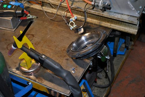 I welded in enough material in the gap so I could get the housing back to the right dimentions after a couple of turns in the mill. 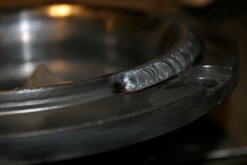 Milling away on the housing, as always I have to use my mill since the lathe is too small.  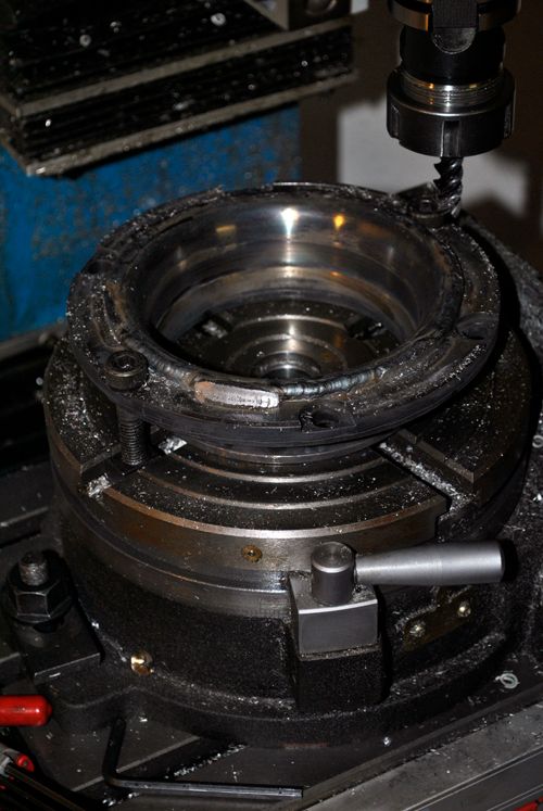 I came upon a neat bench yesterday where I will store the engine parts from now on, no more pile building on the old work bench! Hooray! ;D 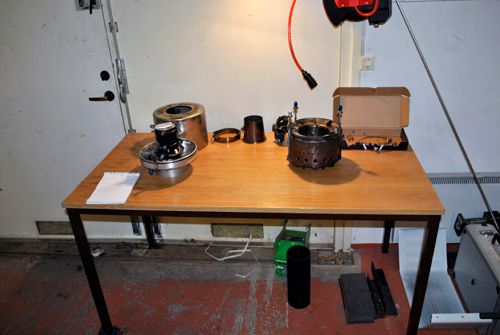 Cheers! |
|
|
|
Post by racket on Jan 18, 2012 18:37:14 GMT -5
Hi Anders
Heh heh , a clean space ..............for now :-)
Did you get any "pulling up" of the flange around where you welded in the filler ??
Lathes are never big enough :-( ......................I had to cut a groove in my lathe bed for one large job , didn't like doing it , but what the heck , it makes for a conversation topic ;-)
Cheers
John
|
|
|
|
Post by Johansson on Jan 19, 2012 0:57:31 GMT -5
Hi John, The flange did pull up a couple of .10´s, I didn´t have time to correct it yesterday but will do so before I coat it and fit it to the engine. In case there is some slight leakage between the turbine housing and the NGV plate the result should be that compressor discharge air will leak into the turbine area and not the other way around because of the pressure drop over the NGV. A minor leakage there would perhaps even help the mild steel housing survive by film cooling. Cheers! |
|
|
|
Post by racket on Jan 19, 2012 2:05:53 GMT -5
Hi Anders
The air is going in the right direction , thats OK , I was just a bit worried it might have caused a leak out of the can ...............I always seem to end up with a big job refacing everything after a simple weld.
Cheers
John
|
|
|
|
Post by Johansson on Jan 26, 2012 17:33:24 GMT -5
Hi guys! Tonight I got a couple of hours of work done on the JU-01 so now the engine is more or less back together again. 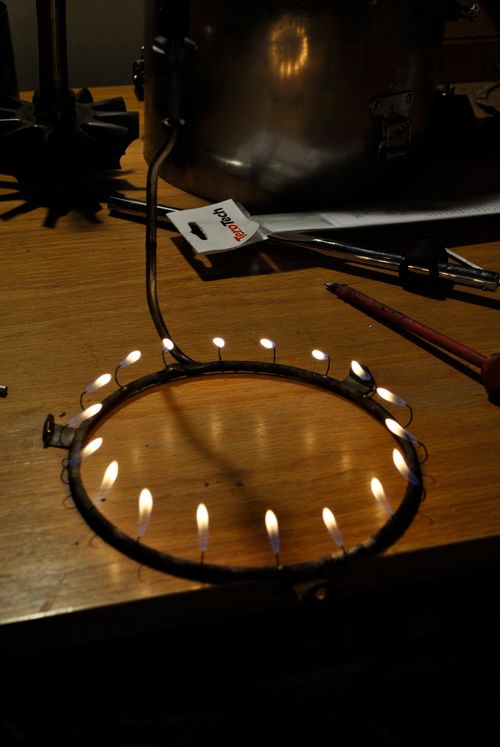 I gave the syringes a better bend at the end to make the fuel hit the vapour tube wall at a sharper angle, luckily I did this because I found one syring that had come loose from the silver solder. Must have missed while bracing so it was only the flux holding it in place. 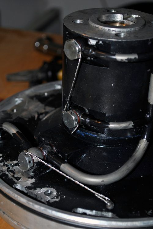 Then I wire locked all bolts and torqued the NGV bolts down with Locktite, after that it was time to fit the turbine shaft. 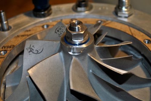 There is no chance in hell that the compressor nut comes off now, torqued to Garretts specs with a generous blob of Locktite should hold it in place until the seas have dried up and the mountains have turned to gravel... ;D Cheers! |
|
|
|
Post by racket on Jan 26, 2012 19:59:52 GMT -5
Hi Anders
LOL, you've got blue Loctite ............I'm still still using the old red stuff :-(
Injectors nice and uniform .
With your gasket between comp wheel cover and comp housing cover , is there a chance of incorperating an O ring into the OD of the wheel cover recess face to produce an extra seal just in case theres some leakage thru the "paper" gasket.
She'll be ready to fire up again in no time at all :-)
Cheers
John
|
|
|
|
Post by Johansson on Jan 27, 2012 1:09:13 GMT -5
As you can see I gave the syringes an extra bend at the tip, before they had a radius but the added knee should force the fuel up against the evaporator wall no matter how much air is flowing past it. I could mill an O-ring groove in the diffusor cover but that would mess up the whole idea of the paper gasket shimming of the comp housing, it is such a tight fit that I cannot imagine that it needs to be sealed further. Cheers! |
|
|
|
Post by Johansson on Jan 27, 2012 17:36:34 GMT -5
Tonight it was all fun and games in my workshop.  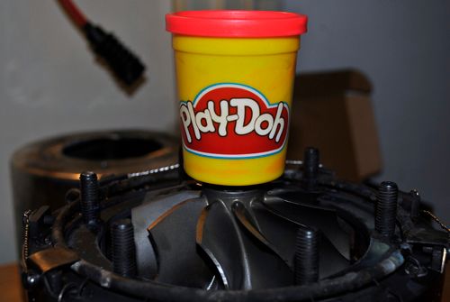 I measured the turbine clearance with it, no clay willies made at all believe it or not. 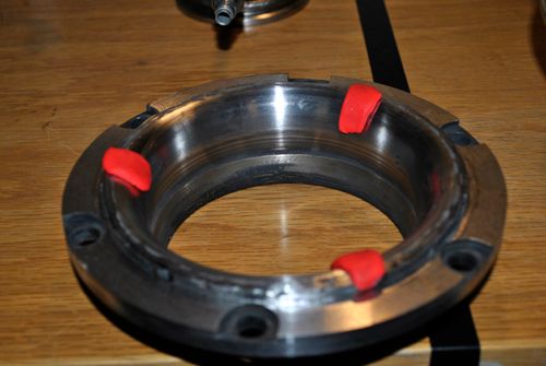 I found that the inducer tips have 0.8mm clearance which narrows down to 0.6mm at the end of the radius, sounds fair enough to me. 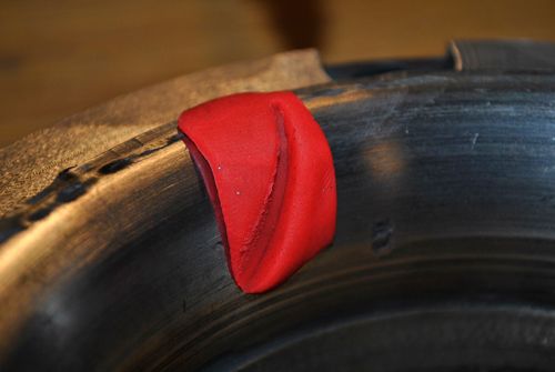 After that I trued the outer side of the turbine housing flange on the lathe, it had warped a bit during the welding I did earlier so I had to trim it some to assure a good seal for the engine cover. 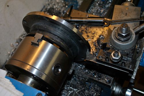 Here it is fitted to the engine, a nice snug fit and I cannot make the turbine wheel scrape the housing no matter how I try. Next up is to sand blaster it and put a new layer of cheramic coating on it. 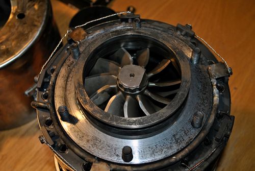 Cheers! |
|
|
|
Post by racket on Jan 27, 2012 18:08:25 GMT -5
Hi Anders
What ......not even one willy ;-)
There shouldn't be any rubbing now
Cheers
John
|
|
|
|
Post by Johansson on Jan 28, 2012 15:45:45 GMT -5
Nope, I hope this doesen´t mean I am getting old and boring... I sand blasted the turbine housing today and a couple of hours ago I coated it with cheramic. 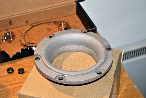 This cheramic stuff is really wonderful, I haven´t even used up half a can yet and it survives in my NGV despite hot starts and around 900°C. No signs of damage to the mild steel housing at all so I cannot but recommend it.  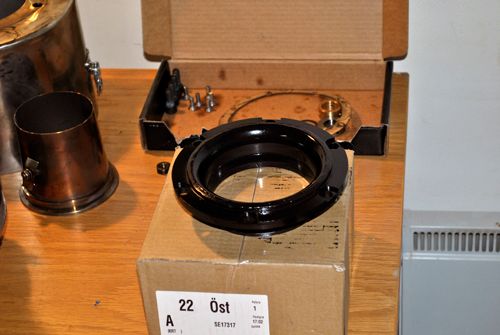 Before I fit the engine to the test stand I will put it on the scale to see how much it weighs, what did your 10/98 weigh in at John? Cheers! |
|
|
|
Post by racket on Jan 28, 2012 16:59:54 GMT -5
Hi Anders
The 10/98 came in under 20 kgs even when packaged up ready to sent via the postal system which has a 20 kg limit . .................probably ~18-19 kgs for the bare motor .
Man those bits look nice with a coat of spray.
Boring you'll never be ;-)
Cheers
John
|
|


