|
|
Post by pitciblackscotland on Jun 3, 2012 3:52:36 GMT -5
Hi Anders, Nice start up, shame the rev counter didn´t work i was looking forward to see how it went  congratulations mate  Cheers, Mark.. |
|
|
|
Post by Johansson on Jun 3, 2012 6:37:08 GMT -5
Thanks a lot guys!
It sure feels like I am beginning on the next chapter now, up until now things have been the old familiar thrust routine but now I am entering new grounds with the shaft power extraction.
Fun fun fun! =)
|
|
|
|
Post by racket on Jun 3, 2012 18:32:24 GMT -5
Hi Anders
2.6 bar -3.6PR , getting pretty close to 100% rpm , could even be there if your NGV is allowing the comp to flow a bit more than the "best efficiency" flow .
Yep , time to get into the freepower :-)
Cheers
John
|
|
|
|
Post by Johansson on Jun 4, 2012 2:40:27 GMT -5
Perhaps just as well that I didn´t push it further then. |
|
|
|
Post by stoffe64 on Jun 4, 2012 2:44:39 GMT -5
CONGRATULATIONS MATE,WELL DONE!!
i would be very interesting to see your engine run,i have only seen it once when you were building it,cant wait for more of your work!
|
|
|
|
Post by ernie wrenn on Jun 4, 2012 7:58:49 GMT -5
Did you leave finger prints on the combustion chamber or was that your way of signing the case?
ernie
CONGRATS!
|
|
|
|
Post by Johansson on Jun 4, 2012 8:37:39 GMT -5
Thanks Stoffe! You are welcome any time, unfortunately there won´t be any more test runs for a while now but it might still be a little more interesting bits and pieces to see now compared to when you visited last time. Ernie: He he, I was actually checking if the vibrations I had during the last run had disappeared. A fraction of a second too late did I remember that with a PR of 3:1 the engine casing gets quite hot... Thanks! |
|
|
|
Post by Johansson on Jun 4, 2012 14:11:02 GMT -5
Yesterday evening I fitted the engine in the bike frame, hopefully for good. 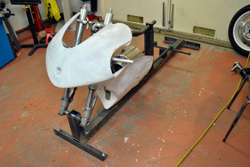 In front of the intake there will be an air box that sucks air from above the front fender, and behind the engine there will be the ducting for the power turbine and the gearbox, so I assume it will be a tight fit in the frame... ;D 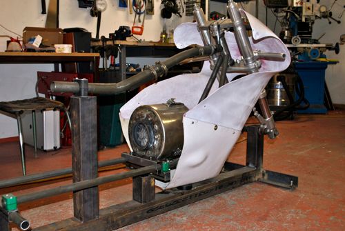 To be able to fit the power turbine I had to remove the frame jig section that secures the upper frame tube, will have to figure out a better jig design for that later. 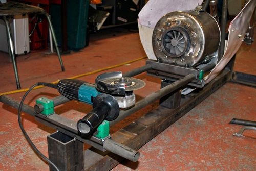 To make sure nothing falls into the engine during the PT build I blocked off the intake and exhaust with some tape. 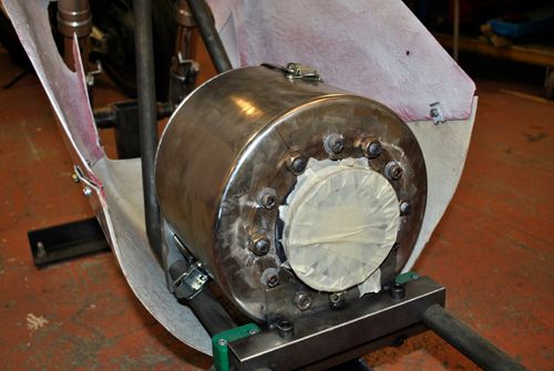 Cheers! |
|
ashpowers
Veteran Member

Joined: February 2011
Posts: 207
|
Post by ashpowers on Jun 4, 2012 15:24:21 GMT -5
Hi Anders,
Congratulations on a successful bench test! Looks like she is running very well!
As for the tach pickup, I had the same problem with my optical tach for the jet scooter. With the sunlight on the IR transistor it will not be able to clearly discern between the laser and the sunlight and the transistor simply completes the circuit.
What I have considered doing is making a custom compressor nut that has a hole all the way through it, radially. The laser will point directly into this hole with the beam running perpendicular to the rotor shaft. As the rotating group spins, this hole will allow the beam to pass through to the other side of the inlet duct, where you can mount your IR transistor about a 1/2" into a tube where it will be in a "shadow" where ambient light cannot easily get into it. The difference in illumination between the blocked laser light and direct laser light should be more than ample to allow the IR transistor to switch properly.
You will have to divide the pulses by 2 since you will be getting 2 pulses per revolution, but that shouldn't be terribly difficult to do. I used a decade counter in the T04 engine so I got a divide by 10 which dropped the pulse frequency down low enough for an LM2917 frequency to voltage converter's input.
Hope this helps, and big congratulations on the successful run! You deserve it! =)
|
|
|
|
Post by Johansson on Jun 4, 2012 15:57:42 GMT -5
Thanks a lot Ash! I hope to hear your engine live and screaming before the JU-01 is operational again. =)
We will have to do some thinking about the rev counter, once the intake ducting is in place sunlight won´t be a problem any more so hopefully it´ll be an easy fix.
I am kind of reluctant to the idea of adding anything to the rotating shaft, we tried a drilled through spinner on the S500 jetkick turbine but got a nasty whine probably caused by messed up rotor dynamics. =(
|
|
|
|
Post by turbochris on Jun 4, 2012 19:15:14 GMT -5
that thing is gonna haul ass
|
|
ashpowers
Veteran Member
Joined: February 2011
Posts: 207
|
Post by ashpowers on Jun 6, 2012 8:09:19 GMT -5
Hi Anders,
Probably will be fine once you install the inlet ducting/filter setup. =)
Looking forward to your progress!
-Ash
|
|
|
|
Post by Johansson on Jun 6, 2012 15:55:52 GMT -5
I think so too. I removed the V-band flange from the jet nozzle and bolted it to the engine to take some measurements, I would have saved the nozzle intact if the flanges weren´t so damn expensive. 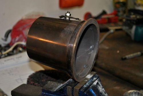 Flange fitted to JU-01. 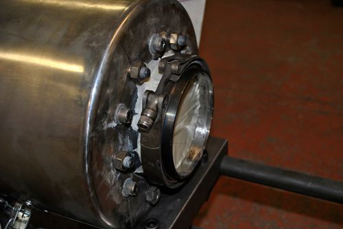 After that I could start doing some trial-and-error drawings in Autocad, even the old 2D cad is very useful to get a grip on what dimentions that should work. If it looks good it will work is my motto during this build. ;D 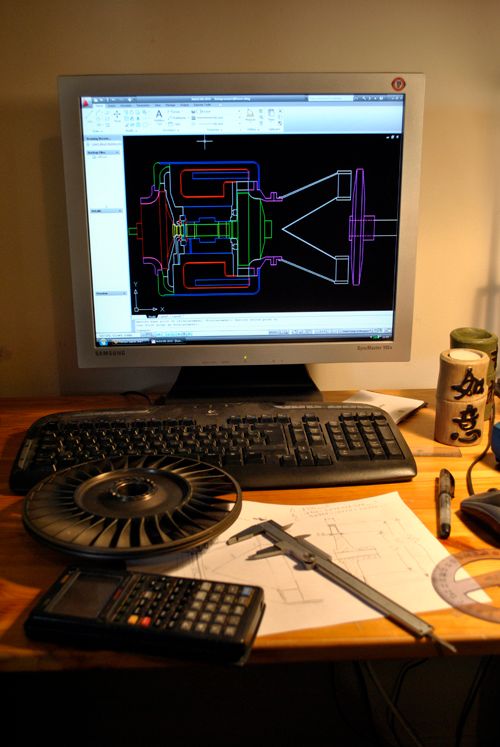 Yeah yeah I know that Ash makes much nicer drawings than I, rub it in will you!  ;D |
|
ashpowers
Veteran Member
Joined: February 2011
Posts: 207
|
Post by ashpowers on Jun 6, 2012 17:54:23 GMT -5
Hi Anders, Hah, Looking good man! If you can send me the AutoCad file you have, I can import that into SW and snazz it up for ya if you like. -Ash |
|
wolfdragon
Senior Member
Joined: April 2011
Posts: 287
|
Post by wolfdragon on Jun 6, 2012 18:57:56 GMT -5
Nice calculator, I have one of those too...
|
|


 congratulations mate


 ;D
;D